Amplification and Audio Connectors
The Amie-Sub drivers are powered by a proprietary open-loop, class D amplifier. The audio signal is processed with electronic crossover, and correction filters for flat phase and frequency responses, and by driver protection circuitry. The amplifier has peak and rms limiters that prevent driver over-excursion and regulate voice coil temperatures.
The standard Amie-Sub user panel includes a 3-pin XLR-F Input and 3-pin XLR-M Loop output connectors for audio, and Limit and Active LEDs, as shown in the figure below.
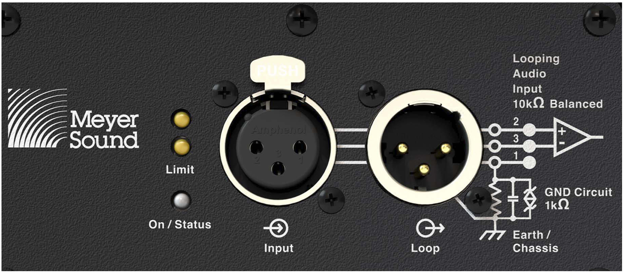 |
Amie-Sub Standard User Panel
Audio Input (XLR 3-Pin Female)
The XLR 3-pin female Input connector accepts balanced audio signals with an input impedance of 10 kΩ. The connector uses the following wiring scheme:
Pin 1 — 1 kΩ to chassis and earth ground (ESD clamped)
Pin 2 — Signal (+)
Pin 3 — Signal (–)
Case — Earth (AC) ground and chassis
Pins 2 and 3 carry the input as a differential signal. Pin 1 is connected to earth through a 1 kΩ, 1000 pF, 15 V clamped network. This circuitry provides virtual ground lift for audio frequencies while allowing unwanted signals to bleed to ground. Make sure to use balanced XLR audio cables with pins 1–3 connected on both ends. Telescopic grounding is not recommended and shorting an input connector pin to the case may cause a ground loop, resulting in hum.
Tip
If the loudspeaker produces unwanted noise or hiss, disconnect its input cable. If the noise stops, there is most likely nothing wrong with the loudspeaker. To locate the source of the noise, check the source audio, AC power, and electrical ground.
Audio Loop Output (XLR 3-Pin Male)
The XLR 3-pin male Loop output connector allows multiple loudspeakers to be looped from a single audio source. The Loop output connector uses the same wiring scheme as the Input connector (see Audio Input (XLR 3-Pin Female)). For applications that require multiple Amie-Sub, connect the Loop output of the first loudspeaker to the Input of the second loudspeaker and so forth.
Note
The Loop output connector is wired in parallel to the Input connector and transmits the unbuffered source signal even when the loudspeaker is powered off.
Calculating Load Impedance for Looped Audio Signals
To avoid distortion when looping multiple loudspeakers, make sure the source device can drive the total load impedance of the looped loudspeakers. In addition, the source device must be capable of delivering approximately 20 dBV (10 V rms into 600 Ω) to yield the maximum SPL over the operating bandwidth of the loudspeakers.
To calculate the load impedance for the looped loudspeakers, divide 10 kΩ (the input impedance for a single loudspeaker) by the number of looped loudspeakers. For example, the load impedance for 10 Amie-Sub is 1000 Ω (10 kΩ/ 10). To drive this number of looped loudspeakers, the source device should have an output impedance of 100 Ω or less. This same rule applies when looping Amie-Sub with other Meyer Sound self-powered loudspeakers.
Note
Most source devices are capable of driving loads no less than 10 times their output impedance.
Tip
Audio outputs from Meyer Sound’s loud- speaker GALAXY Network Platform have an output impedance of 50 ohms. Each output can drive up to 20 Meyer Sound (10 kΩ) loudspeakers without distortion.
Caution
Make sure that all cabling for looped loudspeakers is wired correctly (Pin 1 to Pin 1, Pin 2 to Pin 2, and so forth) to prevent the polarity from being reversed. If one or more loudspeakers in a system have reversed polarity, frequency response and coverage will be significantly degraded.
Optional Integration Input Modules
Two optional integration modules are available for the Amie-Sub loudspeaker: a 7.1 Integration Module and a 2.1 Integration Module (see 2.1 Integration Module Operation).
7.1 Integration Module Operation
The 7.1 Integration Module, shown in the figure below, features industry-standard multi-pin DB-25 female connectors and can be used for 5.1 or 7.1 configurations with third-party, high-quality, 8-channel, DB-25-to-XLR cables (not included).
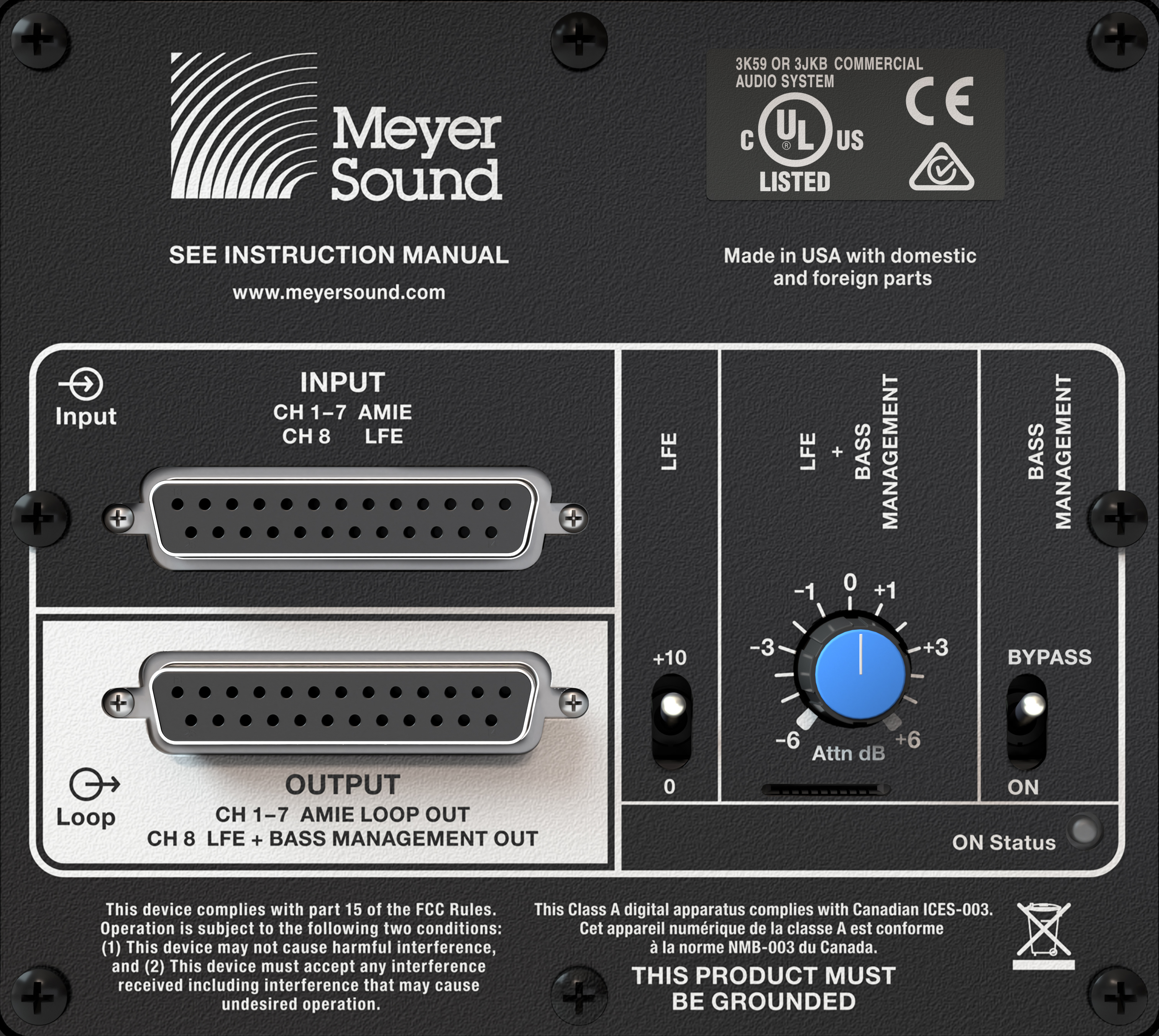 |
7.1 Integration Module
Note
The DB-25 multi-pin female connectors are wired to an analog pinout that has become the standard in the audio industry; it is sometimes referred to as the Tascam® DTRS pinout.
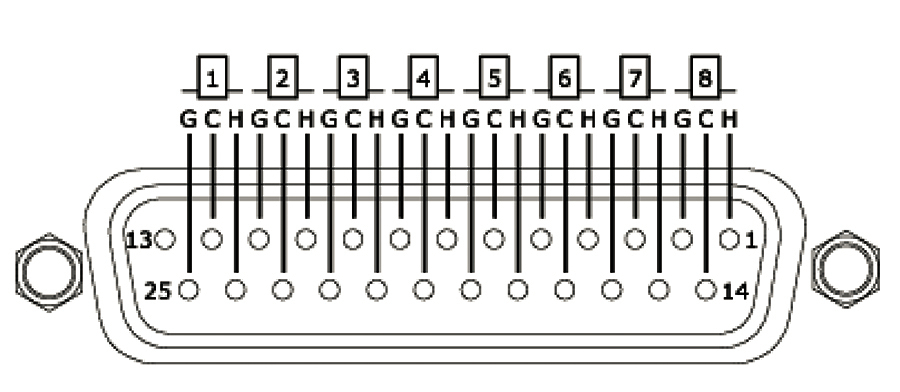 |
DB-25 Pinout (female)
Audio Input (DB-25 female)
The DB-25 input accepts up to seven channels of audio (L, C, R, and Surround) for output to Amie loudspeakers, as well as an LFE input.
Audio Output (DB-25 female)
The DB-25 output provides:
Up to seven channels (L, C, R, and Surround) to drive Amie loudspeakers. These signal paths are passive—no internal processing is performed between input and loop output.
LFE + Bass Management output channel to loop additional Amie-Sub loudspeakers. This output either provides the input passed without any internal signal processing (Bypass mode) or an LFE + Bass Management, internally processed version of the input.
7.1 LFE + Bass Management
For the LFE input, there are three controls on the user panel that affect how this signal is output to the Amie-Sub driver, as shown in the second figure below.
LFE switch: the user can selectively add 10 dB of gain by setting this switch to the “+10 dB” position.
LFE + Bass Management dial: the user can add ±6 dB gain/attenuation to the output of the loudspeaker by rotating this dial to the appropriate position.
Bass Management: When switched to the Bypass position, the signal passes from input to the subwoofer driver without any internal signal processing.
When switched to the ON position, the subwoofer driver receives a combined signal consisting of both channel (L and R) inputs summed, low-pass filtered and then further summed with the (selectively) 10 dB-boosted and then phase-matched (all-pass filtered) LFE input.
The result of this last summation may be boosted or attenuated by the ±6 dB LFE + Bass Management dial.
Note
The option to boost the signal by 10 dB is provided for playback of recorded audio in situations where the LFE channel was recorded 10 dB lower than the other channels and where the source equipment has not already restored this 10 dB.
The purpose of the all-pass filter is to phase-match the LFE channel signal with the low-pass filtered and summed L,C, R and Surround channel signals.
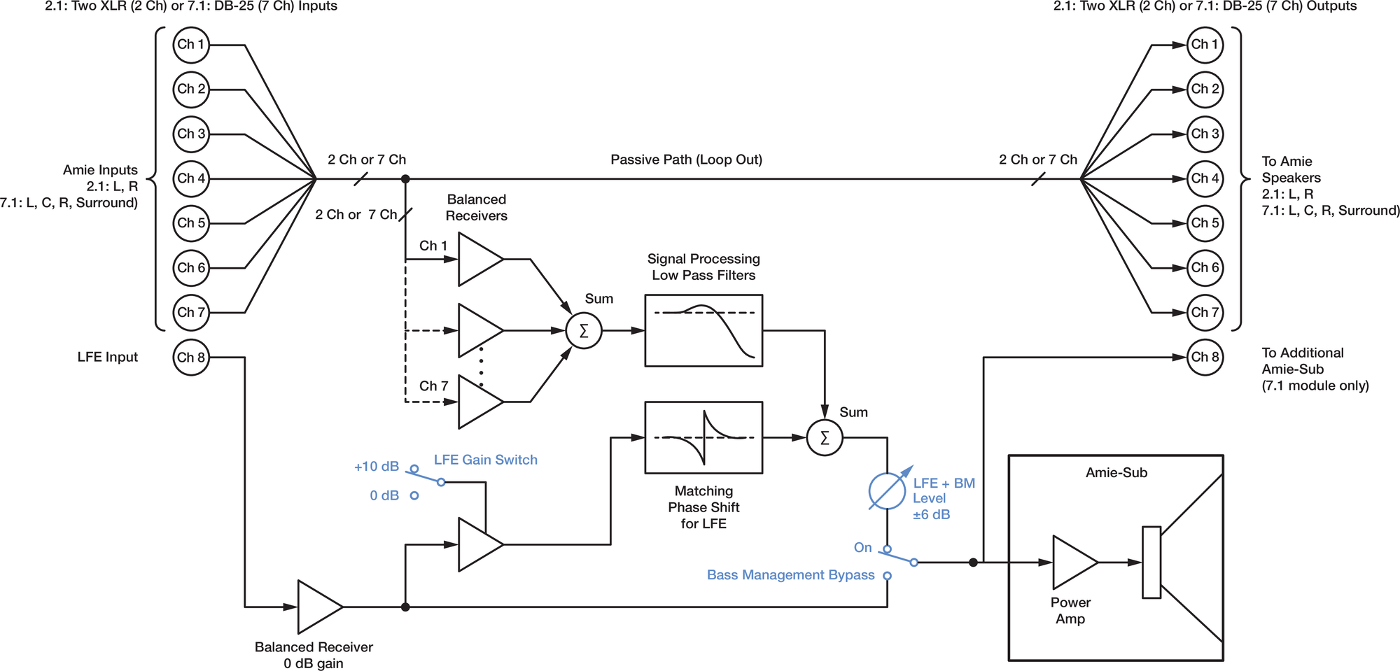
LFE + Bass Management Signal Paths
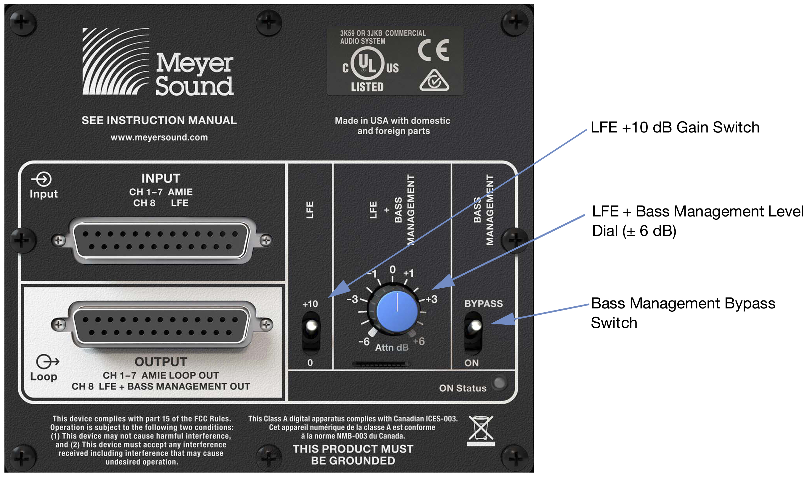 |
Physical Knob and Switches Relating to LFE and Bass Management Control
2.1 Integration Module Operation
The 2.1 Integration Module features two input channels using 3-pin XLR-F connectors (see Audio Input (XLR 3-Pin Female)) and an additional 3-pin XLR-F LFE input, as shown in the figure below.
Two 3-pin XLR-M looping outputs (see Audio Loop Output (XLR 3-Pin Male)) are provided.
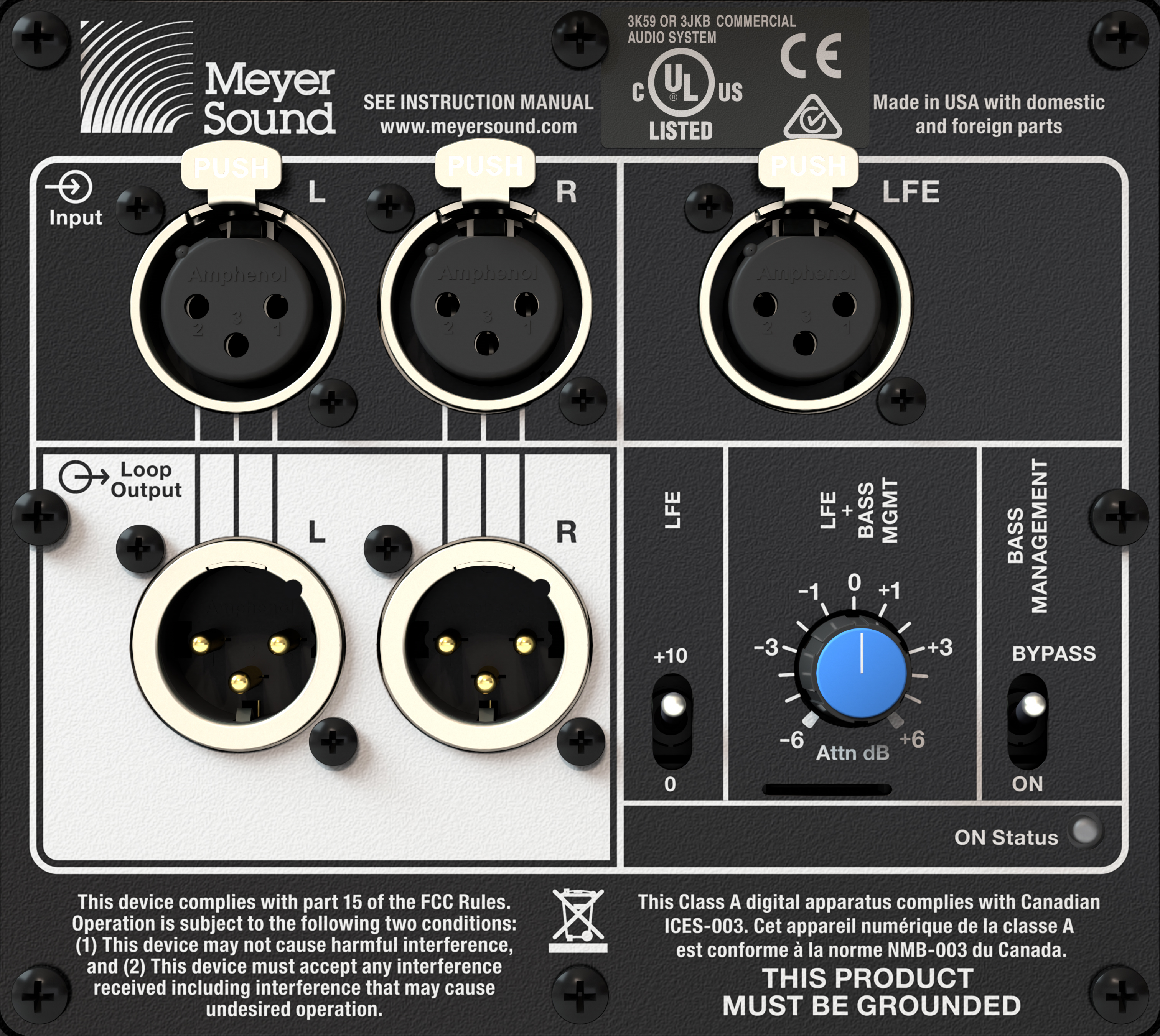
2.1 Integration Module
2.1 LFE + Bass Management
For the LFE input, there are three controls on the user panel that affect how this signal is output to the Amie-Sub driver (see Figure13):
Note
These controls work identically as the ones described for the 7.1 Integration Module except there are only two input channels and no LFE loop output.
LFE switch: the user can selectively add 10 dB of gain by setting this switch to the “+10 dB” position.
LFE + Bass Management Dial: the user can add ±6 dB gain/attenuation to the output (of the internal signal processing path) at the LFE loop output and at the Amie-Sub driver by rotating this dial to the appropriate position.
Bass Management Switch: When switched to the Bypass position, the signal passes from input to the subwoofer driver (and to the output loop) without any internal signal processing.
When switched to the ON position, the subwoofer driver receives a combined signal consisting of both channel (L and R) inputs summed, low-pass filtered and then further summed with the (selectively) 10 dB-boosted and then phase-matched (all-pass filtered) LFE input.
The result of this last summation may be boosted or attenuated by the ±6 dB LFE + Bass Management dial.
Note
The option to boost the signal by 10 dB is provided for playback of recorded audio in situations where the LFE channel was recorded 10 dB lower than the other channels and where the source equipment has not already restored this 10 dB.
The purpose of the all-pass filter is to phase-match the LFE channel signal with the low-pass filtered and summed L, C, R andSurround channel signals.
TruPower Limiting
The Amie-Sub employs Meyer Sound’s advanced TruPower® limiting. Conventional limiters assume a constant driver impedance and set the limiting threshold by measuring voltage alone. This method is inaccurate, because driver impedances change as frequency content in the source material changes, and as thermal values for the loudspeaker’s voice coil and magnet vary. Consequently, conventional limiters often begin limiting prematurely, which reduces system headroom and dynamic range.
In contrast, TruPower limiting anticipates varying driver impedances by measuring both current and voltage to compute the actual power dissipation in the voice coil. This approach improves performance, both before and during limiting, by allowing the driver to produce the maximum SPL across its entire frequency range, while also retaining signal peaks. TruPower limiting also eliminates power compression at high levels over lengthy periods, which helps regulate voice coil temperatures, thereby extending the life of the driver.
LF Limit LEDs
The low-frequency driver for Amie-Sub is powered by the amplifier which includes a limiter. Limiting activity is indicated with one of the two Limit LEDs on the user panel.
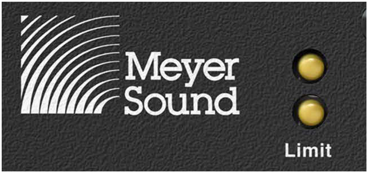 |
Amie-Sub Limit LEDs
When engaged, the limiter not only protects the driver but also prevents signal peaks from causing excessive distortion in the amplifier channel, thereby preserving headroom and maintaining smooth frequency response at high levels. When levels return to normal, below the limiter thresholds, limiting ceases.
Amie-Sub performs within its acoustical specifications at normal temperatures when the Limit LED is unlit, or when the LED is lit for 2 seconds or less and then turns off for at least 1 second. If the LED remains lit for longer than
3 seconds, the loudspeaker enters hard limiting where:
Increases to the input level have no effect
Distortion increases due to clipping
Drivers are subjected to excessive heat and excursion, thereby compromising their lifespan
Caution
The Limit LED indicates when a safe, optimum level is exceeded. If an Amie-Sub loudspeaker system begins to limit before reaching the desired SPL, consider adding more units to the system.
Amplifier Cooling System
Caution
The Amie-Sub loudspeaker is convection-cooled. The amplifier’s heat sink provides natural convection cooling from the air flowing near its fins.
The Amie-Sub heat sink can reach temperatures up to 80° C (176° F) during extreme operation. Wait 15 minutes for the unit to cool before touching it.
On/Status LED
During normal operation, when Amie-Sub is powered on, the On/Status LED is solid green. If the loudspeaker encounters a hardware fault, or the unit begins to overheat, the LED flashes red. In some instances, the loudspeaker will continue to output audio while the LED flashes red, though with a reduction in the limiter threshold and acoustic output to protect the loudspeaker.
If a loudspeaker is overheating, a reduction in SPL may be necessary. If after a reduction in SPL and an appropriate cooling period, the On/Status LED continues to flash red (does not return to solid green), contact Meyer Sound Technical Support.
If the On/Status LED flashes red and the loudspeaker does not output audio, contact Meyer Sound Technical Support immediately.
Caution
If an Amie-Sub loudspeaker system consistently overheats before reaching the desired SPL, consider adding more units to the system.
Note
During startup, the Active/Status LED flashes multiple colors successively. For more information about the power on sequence, see Intelligent AC Power Supply.
The Amie-Sub comes standard with 3/8-inch 16 mounting points on both sides. The Amie-Sub may be mounted on the ceiling with the optional MUB-Amie-Sub U-Bracket.
In addition, an optional black cloth grille frame is available for applications where such an appearance is desired. Details for these optional rigging kits are provided in Amie-Sub Rigging Accessories.