Atmospheric correction
Atmospheric correction overview
The GALAXY processor’s atmospheric correction uses atmospheric loss equations and pre-calculated values to maintain system response as temperature and humidity vary. The correction coefficients are determined by user-entered parameters: the environmental conditions, and unique to each output, atmospheric gain factor and distance.
Air absorption of sound is a complex, non-intuitive function, of which temperature, humidity, and distance have the most effect, changing how well higher frequency sounds propagate through air. The graphs in the figure below indicate a multitude of attenuation scenarios for just a handful of distances.
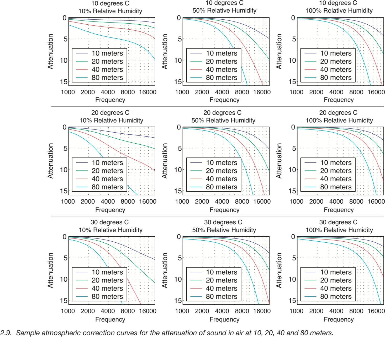
Atmospheric attenuation of sound scenarios
The figure below provides frequency attenuation curve examples for three different temperatures with a fixed distance of 100 meters, at seven values for relative humidity. Depending on the atmospheric conditions and the distance the array is throwing, the number of possible correction combinations can be quite large, but they are achievable with the GALAXY processor.
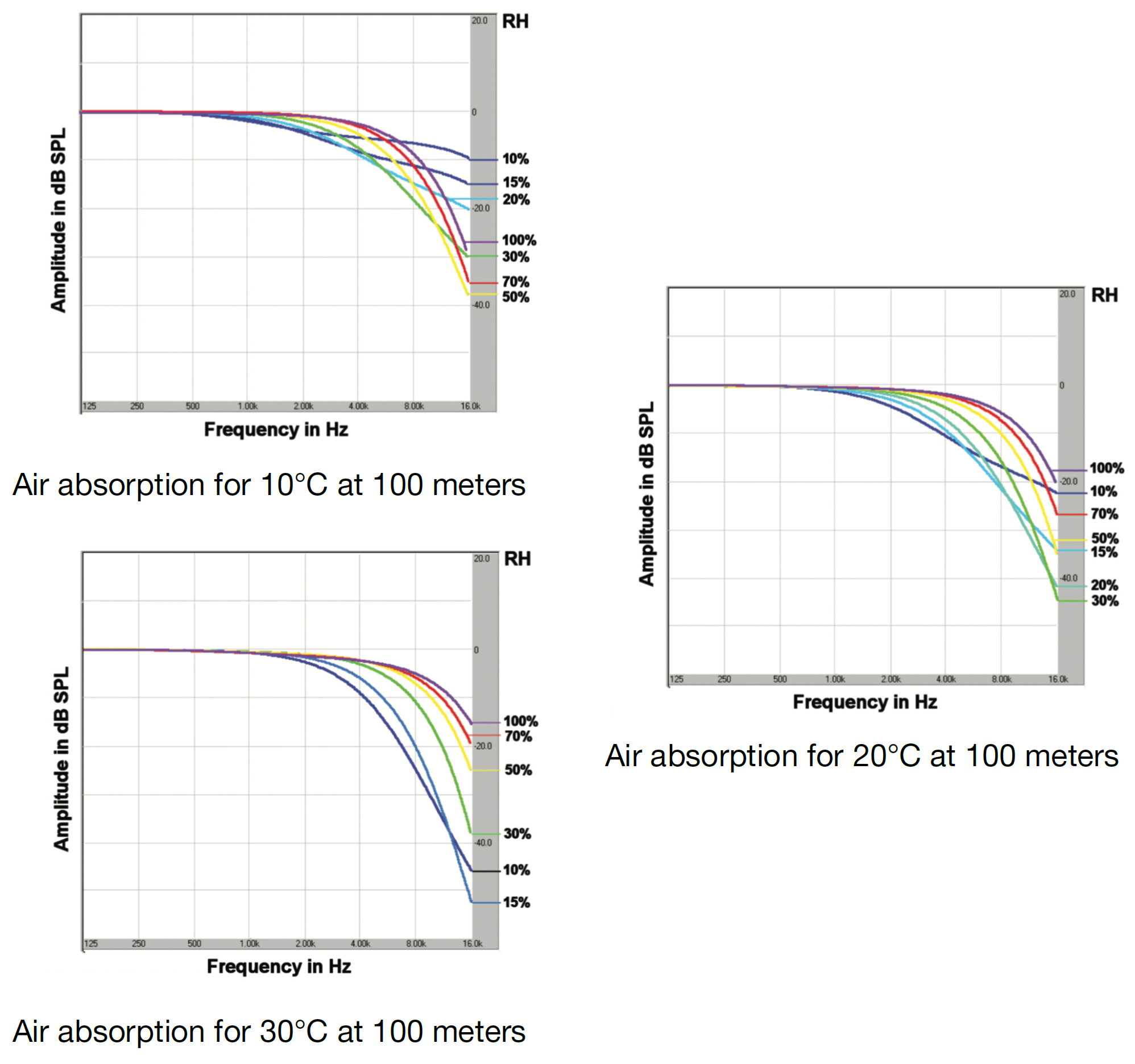
Frequency attenuation curves: 3 temperatures, all at 100 meters, and with seven relative humidity values
The GALAXY processor’s atmospheric correction filter function is limited to a maximum of 14 dB of boost when the atmospheric gain factor is set to 100%. Atmospheric correction does not try to correct to the highest frequencies. It is constrained to the range of frequencies that can be practically corrected, preserving headroom, unlike using a shelving filter.
The figure below provides frequency response curves for four different natural environments. The red curve indicates the frequency absorption due to the location’s atmospheric conditions if left uncorrected. (Note the roll-off at higher frequencies.) The green curve illustrates the frequency response of the atmospheric correction filters for that situation. The blue curve indicates the improved frequency response at higher frequencies for the resulting signal after applying atmospheric correction.
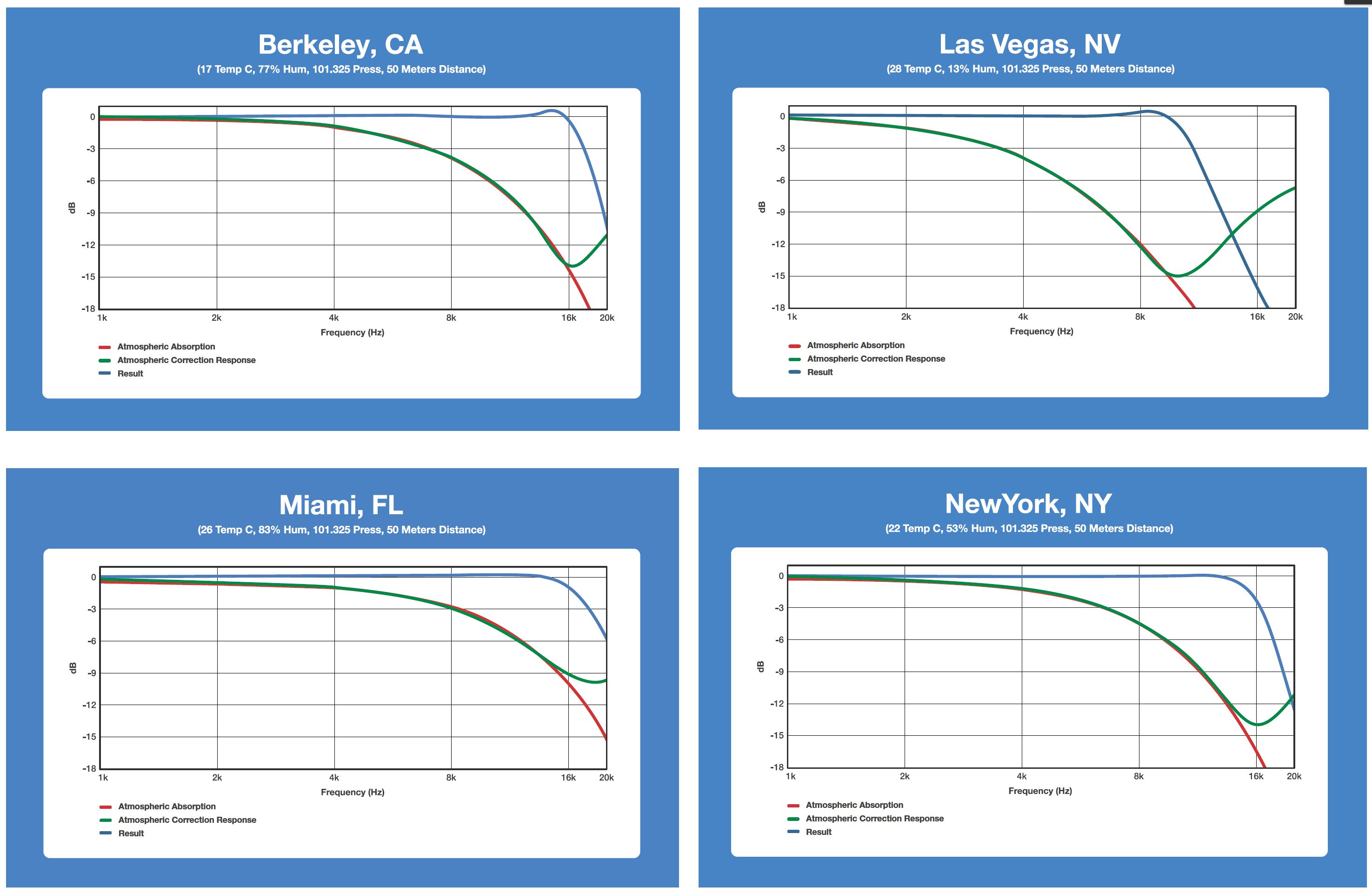
Atmospheric correction results for four different scenarios.
Using the GALAXY processor’s environmental conditions settings
To use the atmospheric correction function, the user must first set the environmental conditions. To do so:
Select a GALAXY processor in Compass.
Select the Settings > Environment tab.
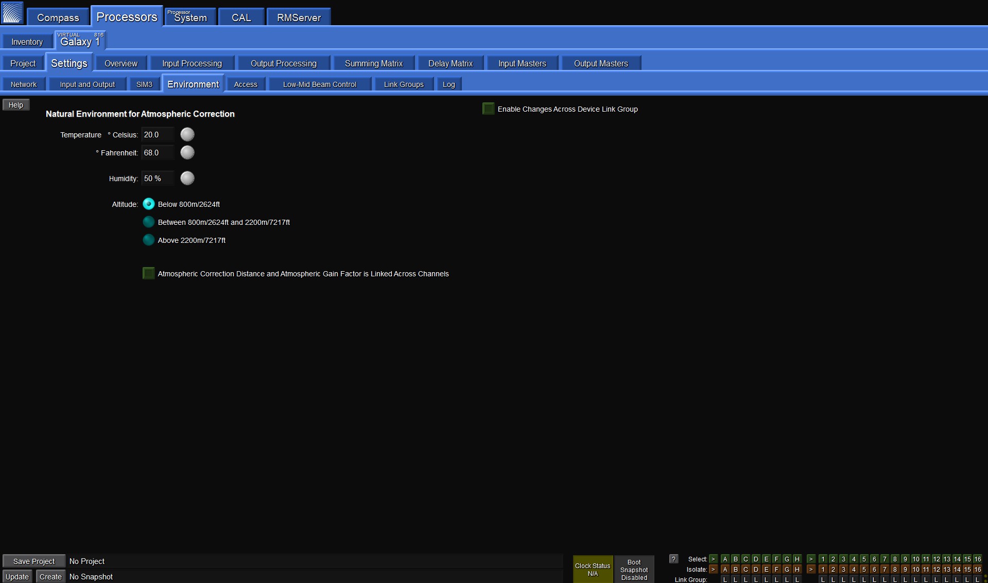
Environment Tab Settings
From this tab you can enter the current temperature and humidity, and select the appropriate altitude range. These values are used to implement the correction filters when atmospheric aorrection is enabled. All three parameters will affect the frequency, bandwidth and gain of the correction filters. These parameters should be adjusted continuously to match the current real-world conditions.
Tip
The ability to control these parameters is also possible from the bottom of the Overview tab.
For example, if a system is calibrated in the morning with atmospheric correction enabled, the environmental parameters should be updated to reflect the actual temperature and humidity throughout the day, maintaining the system response without over-correcting or unnecessarily reducing available headroom of the system.
Tip
A good rule of thumb is to update temperature or humidity settings in the processor if they differ from actual conditions by more than 5° Fahrenheit or 5% humidity.
To set atmospheric correction:
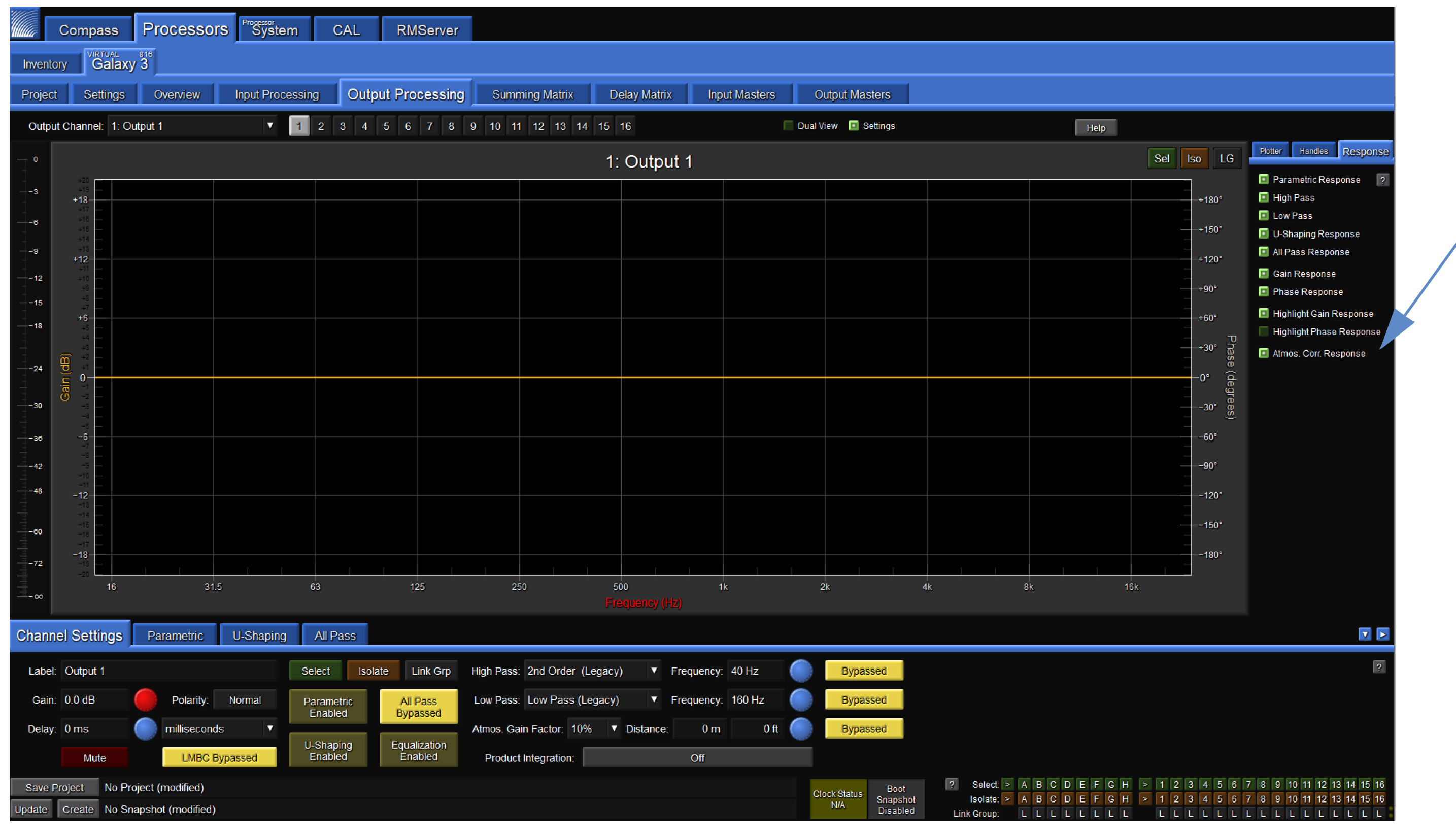
Select an output processing channel under the Output Processing tab. By default, the correction filters will not be shown in the plotter.
To make the filters visible, select the Response mini tab to the right of the plot, and check the box labeled Atmos. Corr. Response.
At the bottom of the window click once on the Bypass/Enable toggle button on the bottom right, next to the Atmos. Gain Factor and Distance settings to enable Atmospheric Correction.
Atmospheric correction response enabled via Response mini tab within the Output Processing tab
Note
Atmospheric gain factor limits the amount of makeup gain added. When set to 100%, the filters are constrained to 14 dB of gain. When set to 50%, correction is limited to 7 dB of gain. Increasing the atmospheric gain factor will reduce headroom.
The Distance parameter should be set to the on-axis distance between the loudspeaker and the nearest listener. For example, it is common for the top element in a line array to be aimed toward listeners further away than the bottom element in the array; different values should be entered accordingly depending on what element in the array is being driven by each output channel. The maximum distance that can be entered is 150 meters (492.1 feet).
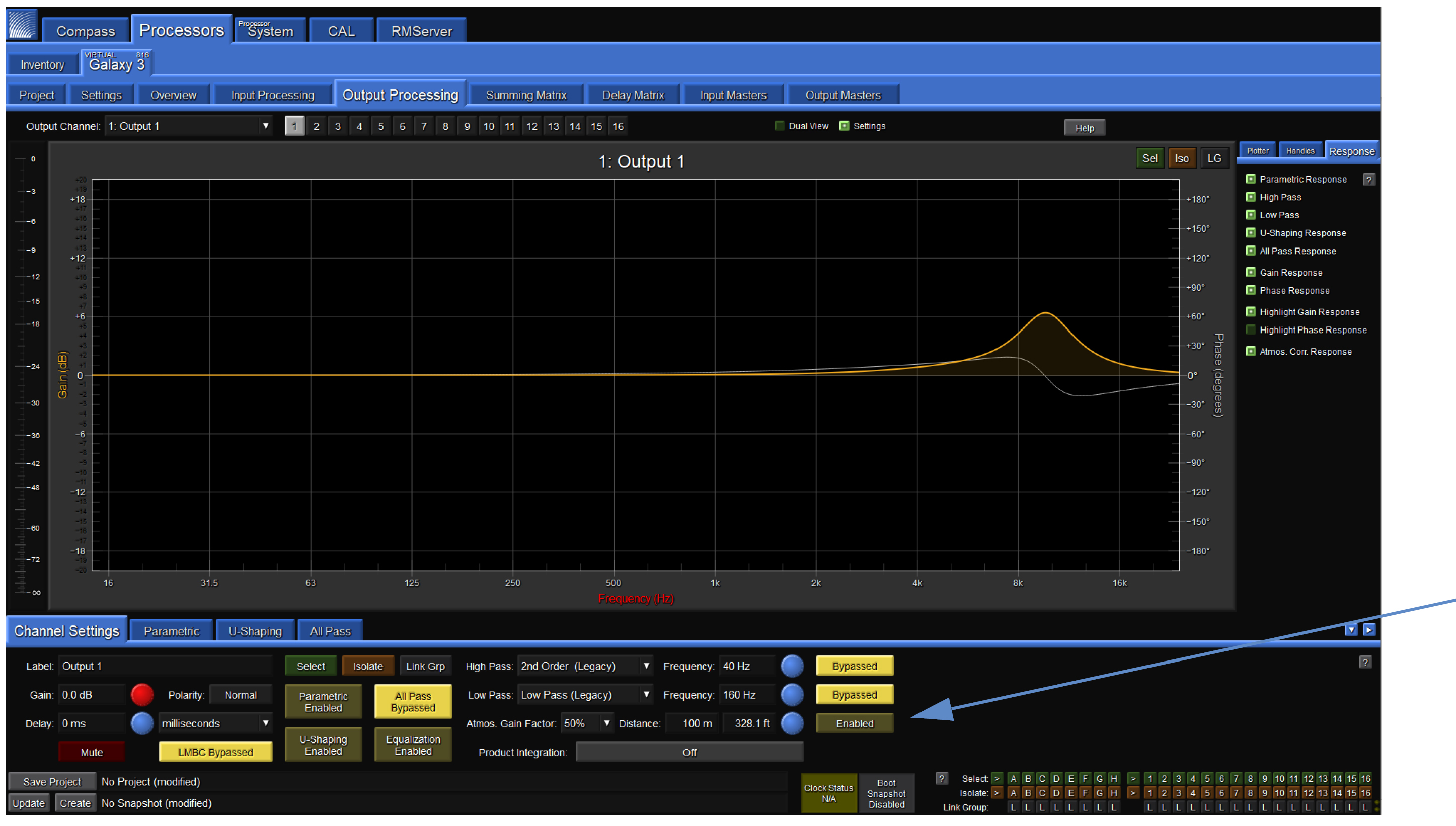
Atmospheric correction enabled and displayed