QuickFly Rigging
Important Safety Considerations
When installing Meyer Sound loudspeakers and subwoofers, the following precautions should always be observed:
All Meyer Sound products must be used in accordance with local, state, federal, and industry regulations. It is the owner’s and user’s responsibility to evaluate the reliability- ability of any rigging method for their application. Rigging should only be carried out by experienced professionals.
Use mounting and rigging hardware that has been rated to meet or exceed the weight being hung.
Make sure to attach mounting hardware to the building’s structural components (roof truss), and not just to the wall surface.
Make sure bolts and eye bolts are tightened securely. Meyer Sound recommends using Loctite® on all threaded fasteners.
Inspect mounting and rigging hardware regularly. Immediately replace any worn or damaged components.
900-LFC Rigging Options
The table below summarizes the available rigging options for the 900-LFC.
Note
For complete information about rigging hardware, including dimensions, weight, configuration, and load ratings, refer to the MG-LEOPARD/900-LFC Assembly Guide (PN 05.243.080.01).
Caution
Always use the MAPP System Design Tool to verify load ratings for a particular application.
Model | Weight | Features | Required Quick-Release Pins | Required Shackles |
|---|---|---|---|---|
MRK-900-LFC rigging kit (PN 40.246.168.01) | — | Allows the 900-LFC to be flown and groundstacked with the MG-LEOPARD/900-LFC grid; includes six captive GuideALinks and eight quick-release pins. | 5/16 x 0.63-inch (black button), PN 134.024, qty 8 included | — |
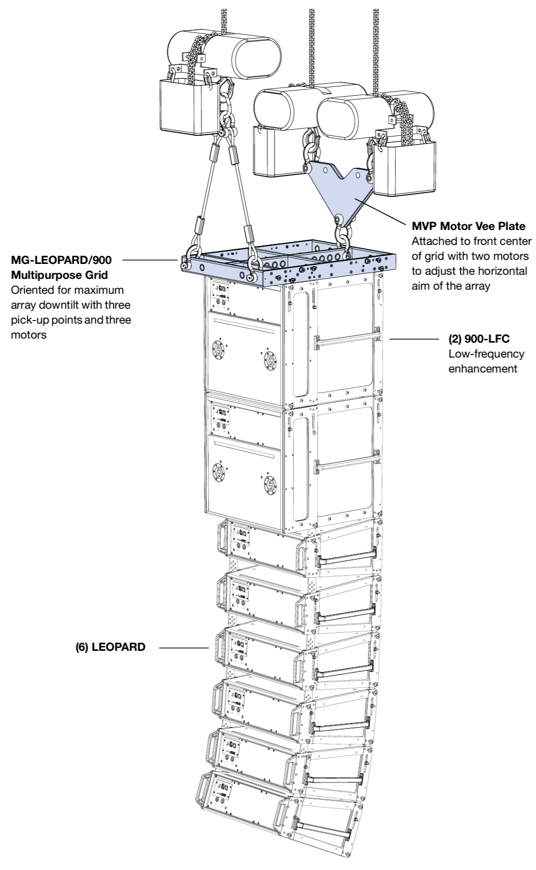
MG-LEOPARD/900-LFC multipurpose grid (PN 40.243.080.01) | 60.5 lb (27.5 kg) | With some restrictions, flies up to 16 900-LFCs at a 5:1 safety factor; supports mixed arrays of LEOPARDs and 900-LFCs without transition hardware; accommodates a variety of pickup configurations with four corner and 13 center pickup points; includes attachment points to accommodate brackets and adapters for lasers and inclinometers; can also be used for groundstacking. | 5/16 x 0.875-inch (red button), PN 134.025, qty 10 included | 5/8-inch or 3/4-inch |
MG-LEOPARD/900-LFC grid tilt kit (PN 40.243.163.01) | 2 lb (0.9 kg) | Includes two angle feet that attach to the rear of the MG-LEOPARD/900-LFC grid that add from 3-8 degrees of tilt to groundstacks. | 5/16 x 0.875-inch (red button), PN 134.025, qty 0 included; see note below. | — |
MPK-POLE-35MM-M20 Adjustable Pole Kit (PN 40.010.973.01) | 8 lb (3.63 kg) | Adjustable length 927–1524 mm (36.5–60 in), 35 mm (1.375 in) pole with assisted lift. Lower shaft fits 35 mm cups or use the removable M20 threaded lug for added stability. Upper shaft includes PAS-M20 Adapter Sleeve to fit loudspeakers with 35 mm and M20 internal pole mounts onto a 35 mm speaker stand. (Can also buy the PAS-M20 Adapter Sleeve separately). Additional 38 mm (1.5 in) adapter included. | — | — |
MVP motor Vee plate (PN 40.215.184.01) | 20 lb (9.1 kg) | Fine tunes the horizontal aim of arrays; compatible with MTG-LEO-M, MTG-LYON, MTG-1100, and MG-LEOPARD/900-LFC grids. | — | 3/4-inch or 7/8-inch |
PBF-LEOPARD pull-back frame (PN 40.243.185.01) | 4.9 lb (2.2 kg) | Attaches to bottom of LEOPARD and 900-LFC arrays (to the bottom cabinet) and provides pull-back for extreme array downtilt; can also be used to add tilt to LEOPARDs groundstacked on the 900-LFC | 5/16 x 0.63-inch (black button), PN 134.024, qty 2 included | 1/2-inch |
MCF-900-LFC caster frame (PN 40.246.130.01) | 46 lb (20.9 kg) | Safely transports up to two 900-LFC cabinets, making it easy to assemble and disassemble arrays in blocks of two cabinets; configurable for cabinets with or without the MRK-900-LFC rigging kit | 5/16 x 0.63-inch (black button), PN 134.024, qty 0 included; see note below. | — |
Note
The MCF-900-LFC caster frame does not include quick-release pins because it is secured with the quick-release pins included with the loudspeaker.
The MG-LEOPARD/900-LFC grid tilt kit does not include quick-release pins because the angle feet are secured with the quick-release pins included with the grid.
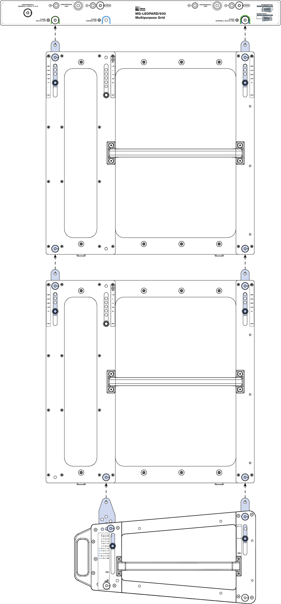
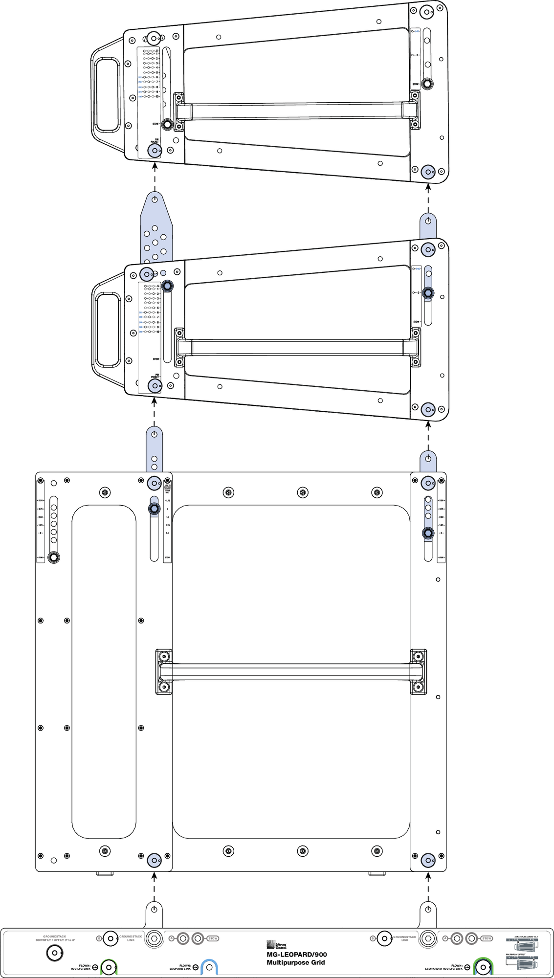
Rigging Example, Mixed Array with 900-LFCs and LEOPARDs
Ground stacking 900-LFC Loudspeakers
900-LFCs can be ground-stacked up to three cabinets high, with or without the MRK-900-LFC rigging kit, as shown in the figure below.
Protective plastic skids are included on the bottom of the 900-LFC cabinet that align with the slots on the cabinet top. Loudspeakers can be stacked normally or reversed for cardioid configurations. When ground stacking 900-LFCs, make sure the skids for each cabinet align with the slots in the cabinet tops. When equipped with the MRK-900-LFC rigging kit, the 900-LFC can be ground-stacked on the MG-LEOPARD/900-LFC grid with LEOPARDs for mixed groundstacks.
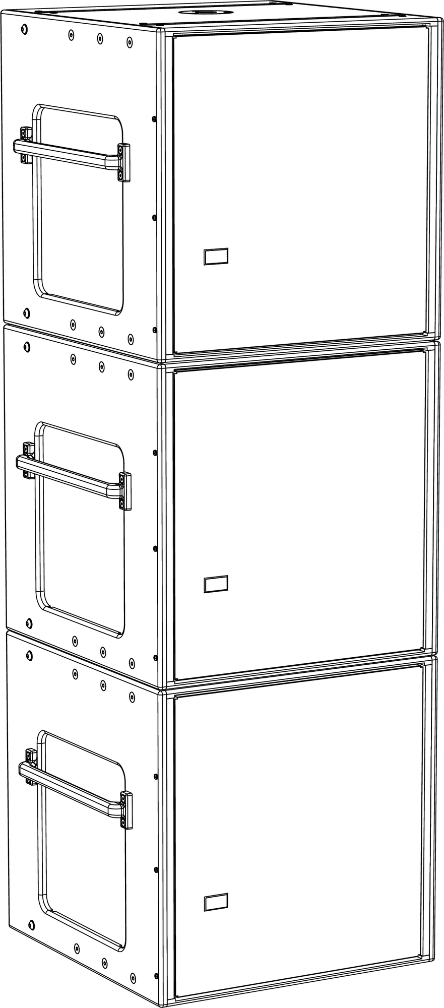
900-LFC Groundstack (Without Rigging)
Caution
As a safety precaution, to avoid tipping, a maximum of three cabinets is supported for groundstacked 900-LFCs.
Note
900-LFCs need not be equipped with the MRK-900-LFC rigging kit for secure ground stacking of up to three cabinets.
900-LFC Cardioid Arrays
The 900-LFC can be configured in cardioid arrays to reduce output heard behind the loudspeakers, as shown in the figure below. The loudspeaker’s linearity ensures that cardioid patterns behave accurately even at very high levels. Cardioid arrays are achieved by placing three loudspeakers coplanar to each other (in either a groundstacked or flown array) with one loudspeaker facing the opposite direction. Polarity and delay processing is applied to the rear-facing loudspeaker, which yields output that cancels output from the other loudspeakers normally present behind the cardioid arrays. For example, on the rear-facing unit, reverse the polarity relative to the front-facing loudspeaker and add 3.8 ms relative to the front-facing units.
900-LFC Cardioid Groundstack (With Rigging)
Note
900-LFCs need not be equipped with the MRK-900-LFC rigging kit for groundstacked cardioid configurations of up to three cabinets.
900-LFC cardioid arrays can also be flown from the MG-LEOPARD/900-LFC grid. For more information, refer to the MG-LEOPARD/900-LFC Assembly Guide (PN 05.243.080.01).
To achieve an accurate cardioid pattern, Meyer Sound’s MAPP System Design Tool and the Galileo® GALAXY Network Platform are required. Use MAPP to calculate the appropriate ratio of forward to rear-facing loudspeakers. A myriad of cardioid and directional configurations are possible and can be calculated and predicted with MAPP. For more information, contact Meyer Sound Technical Support.
MRK-900-LFC Rigging Kit
The optional MRK-900-LFC rigging kit allows the 900-LFC to be flown and groundstacked with the MG-LEOPARD/900-LFC multipurpose grid. The kit also allows 900-LFCs to be flown and ground-stacked with LEOPARD with no transition hardware. The rigging kit is available as a factory-installed option or as a field upgrade and uses rugged GuideALinks and intuitive quick-release pins to securely link adjacent loudspeakers in flown and ground-stacked array configurations.
Note
For more information about the MRK-900-LFC rigging kit, including its kit contents, weight, and installation instructions, refer to the MG-LEOPARD/900-LFC Assembly Guide.
900-LFC GuideALinks
When equipped with the MRK-900-LFC rigging kit, the 900-LFC includes six captive GuideALinks and six mating link slots that link to adjacent loudspeakers in flown and groundstacked arrays. Located at the top of the cabinet,
GuideALinks extend up and into the link slots of the cabinet above it, as shown in the following two figures, or into the link slots of the MG-LEOPARD/900-LFC grid, making it easy to link cabinets when they are stacked. GuideALinks extend and retract with knobs and are secured with two quick-release pins: one each in the top and bottom cabinets. GuideALinks accommodate reversed loudspeakers for cardioid arrays.
The MRK-900-LFC rigging kit includes eight 5/16 x 0.63-inch quick-release pins (black button) (PN 134.024).
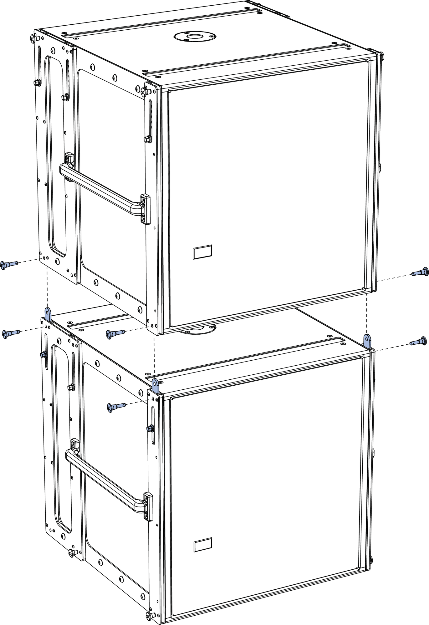
900-LFCs with MRK-900-LFC Rigging Kit, GuideALinks, Exploded View
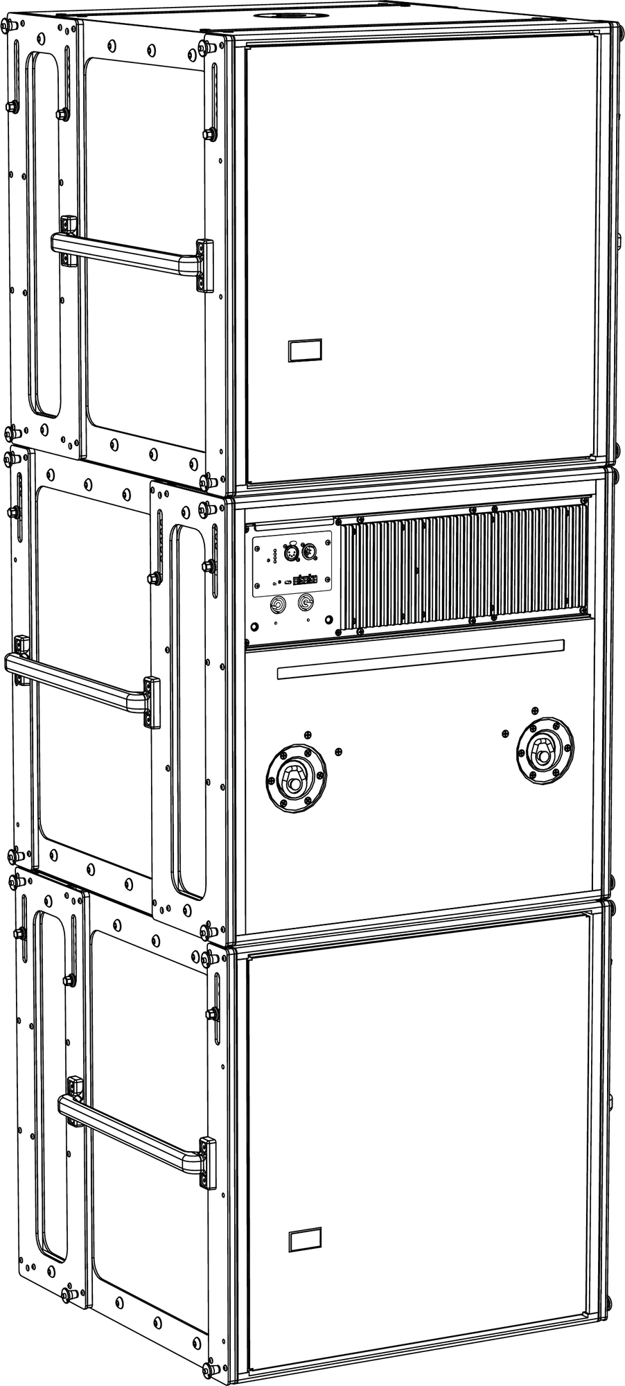
The 900-LFC’s GuideALinks accommodate both 900-LFCs and LEOPARDs without transition hardware. The front and rear GuideALinks are used when flying the 900-LFC below the MG-LEOPARD/900-LFC grid, or when flying it below another 900-LFC, as shown in the figure below. The configuration of the 900-LFC’s GuideALinks, front and rear, determines its splay angle.
Flown 900-LFC with GuideALink Attachments
The 900-LFC’s four corner link slots on the bottom of the cabinet accept GuideALinks from flown 900-LFCs. The front and middle link slots accept LEOPARD GuideALinks when flying LEOPARDs below the 900-LFC, as shown in the figure above. The configuration of LEOPARD’s GuideALinks, front and rear, determines its splay angle.
The 900-LFC’s front and middle link slots also accept links from the MG-LEOPARD/900-LFC grid when groundstacking the 900-LFC, as shown in the figure below. The configuration of the grid’s links, whether set to A or B, determines the angle of attachment for the groundstacked 900-LFC.
Groundstacked 900-LFC with GuideALink Attachments
The 900-LFC’s front and middle GuideALinks are used when attaching a LEOPARD groundstack on top of the 900-LFC, as shown in the figure above.
Caution
Do not use the middle GuideALinks when flying the 900-LFC below the MG-LEOPARD/900-LFC grid or when flying below another 900-LFC. Always use the front and rear GuideALinks when flying the 900-LFC.
Note
When flying the 900-LFC below the MG-LEOPARD/900 grid, a splay angle of 0 degrees is recommended for the top cabinet (rear GuideALinks set to 0, front GuideALinks set to 0) to ensure that the cabinet aligns with any lasers or inclinometers mounted on the grid. To add tilt to the top cabinet, the actual grid should instead be tilted. For more information, refer to the MG-LEOPARD/900 Assembly Guide (PN 05.243.080.01).
900-LFC Splay Angles
The front and rear GuideALinks attach at angles of 0.00, 1.25, 2.50, 3.75, or 5.00 degrees, thereby allowing curved arrays for the 900-LFC. Because the cabinet and front and rear GuideALinks are symmetrical, the curved arrays can also include cardioid configurations.
The labels next to the front, as shown in the figure below, and rear GuideALinks indicate the splay angle between cabinets (when the opposing links are set to 0 degrees). As the links are moved up, the splay angles increase. To stow the GuideALinks, move them all the way down to STOW and pin them.
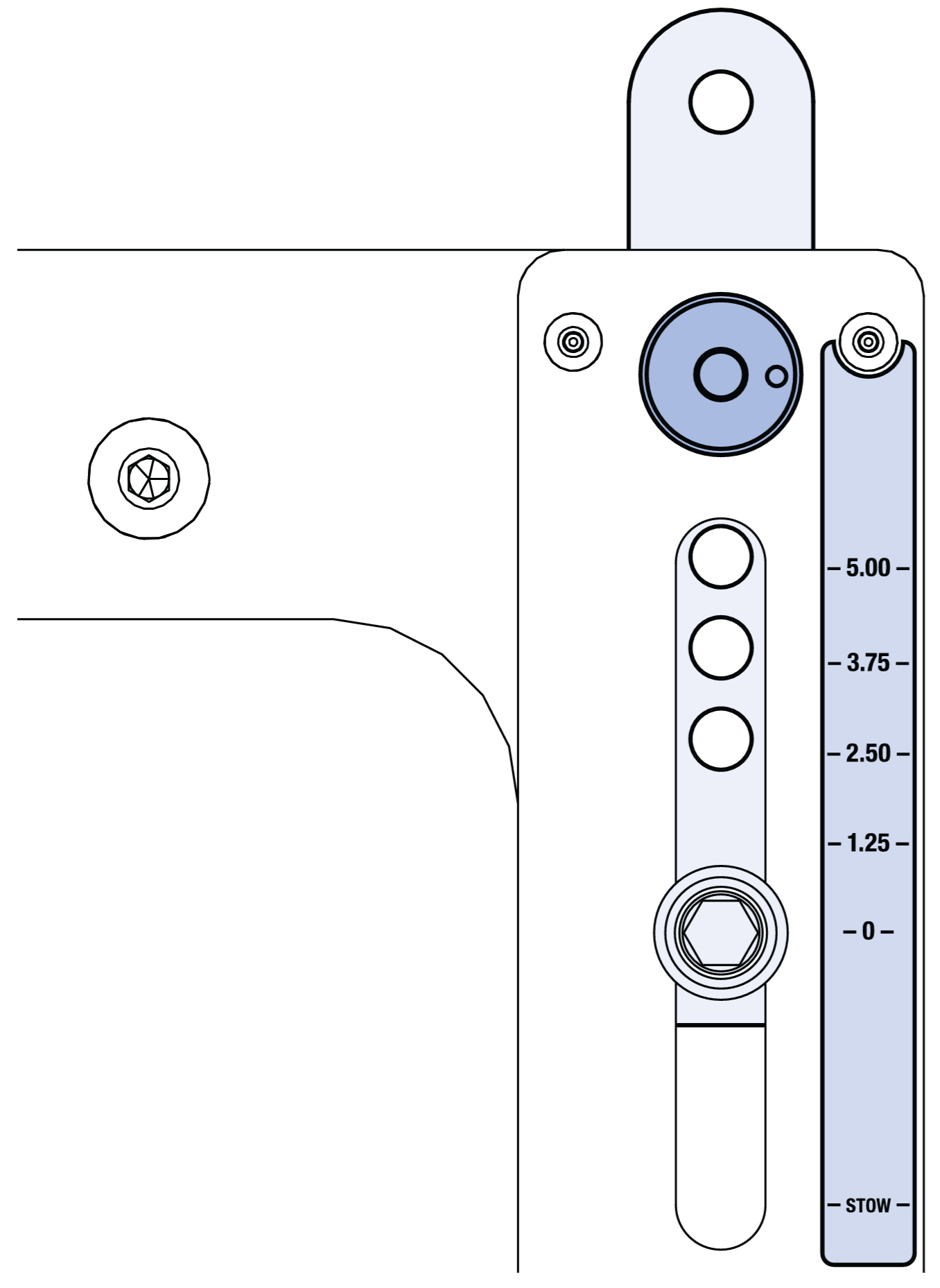
900-LFC Front GuideALinks Label
Note
Curved 900-LFC arrays do not provide directionality for low-frequency content. The curved array capability of the 900-LFC is provided for aesthetic reasons, to complement, if desired, the curvature of LEOPARD, LYON, and LEO-M arrays and to not potentially shadow the HF output of an adjacent array.
Pole-mount Receptacle
You can mount a Meyer Sound loudspeaker on top of the 900-LFC with a third-party heavy-duty pole and pole-mount
adapter, shown in the figure below. The 900-LFC includes a 38 mm (1.5 in) (U.S.) or 35 mm (1.38 in) (E.U.) pole-mount receptacle.
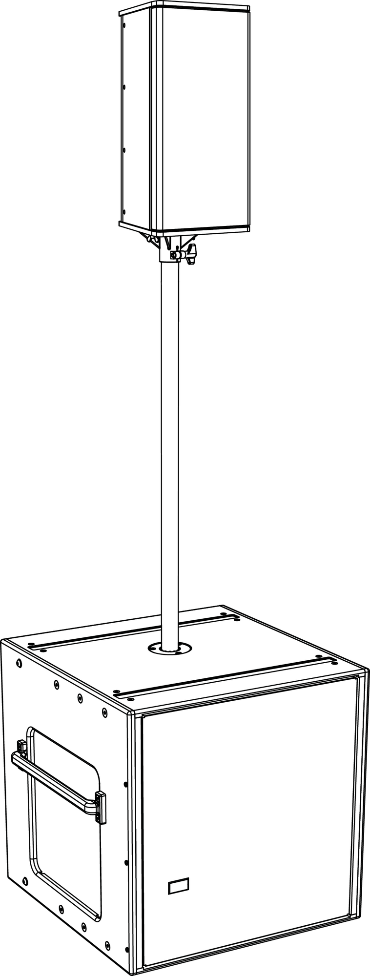
900-LFC with Pole and Pole-Mount Adapter
The following Meyer Sound loudspeakers can be mounted on top of the 900-LFC. Make sure that the pole and pole-mount adapter can support the weight of the mounted loudspeakers
and that they are installed according to the manufacturer’s instructions.
(1) ULTRA-X40/42 (55 lb, 25 kg)
(1) UPA-1P or UPA-2P (77 lb, 34.9 kg)
(1) UPJ-1P (46 lb, 20.9 kg)
(1) UPJunior (28 lb, 12.7 kg)
(2) UPJuniors with MUB-UPJunior U-bracket and MAAM-UPJunior array adapter (70 lb, 31.8 kg)
Caution
Make sure the pole and pole-mount adapter can support the total weight of the mounted loudspeakers. In particular, heavier loudspeakers are less stable on taller pole mounts. Observe all safety precautions specified by the pole manufacturer.
MAPP System Design Tool
The MAPP System Design Tool is a powerful, cross-platform application for accurately predicting the coverage pattern, frequency response, phase response, impulse response, and SPL capability of individual or arrayed Meyer Sound loudspeakers.

MAPP System Design Tool
Whether planning for fixed installations or for tours with multiple venues, use MAPP to accurately predict the appropriate loudspeaker deployment for each job, complete with coverage data, system delay and equalization settings, rigging information, and detailed design illustrations. MAPP’s accurate, high-resolution predictions ensure that systems will perform as intended, thereby eliminating unexpected coverage problems and minimizing onsite adjustments.
The key to the accuracy of MAPP’s predictions is MeyerSound’s exhaustive database of loudspeaker measurements. Performance predictions for each loudspeaker are based on 3-dimensional, 65,000+ 1/48th-octave-band measurements taken in the MeyerSound anechoic chamber. The extraordinary consistency between Meyer Sound loudspeakers guarantees that predictions from MAPP will closely match their actual performance.
MAPP software allows for configuration of MeyerSound loudspeaker systems and definition of the environment in which they operate, including air temperature, pressure, humidity, and the location of prediction surfaces. Importing both CAD (.DXF) and Sketchup (.SKP) files containing detailed venue information to act as an anchor model to the prediction surfaces and a visual aid to facilitate prediction data interpretation is also possible.
Tip
See meyersound.com for support and more information about MAPP.
MAPP Capabilities
With MAPP, you can:
Simulate different loudspeaker configurations to refine system designs and determine the best coverage for intended audience areas
Model loudspeaker interactions to locate constructive and destructive interferences so that loudspeakers can be re-aimed and repositioned as necessary
Place microphones anywhere in the Model View space and predict loudspeaker frequency response, phase response, and sound pressure levels at each microphone position
Determine delay settings for fill loudspeakers using the Inverse Fast Fourier Transform and phase response feature
Preview the results of signal processing to determine optimum settings for the best system response
Automatically calculate load information for arrays to determine necessary minimum rigging capacity, front-to-back weight distribution, and center of gravity location
Generate and export system images and system PDF reports for client presentations
Synchronize GALAXY processor output channel settings in real-time with virtual or real GALAXY units, allowing in-the-field changes to be predicted during system alignments.
Galileo GALAXY Network Platform
The Galileo GALAXY Network Platform is a sophisticated loudspeaker management tool for controlling all MeyerSound speaker types. The GALAXY loudspeaker processor extends a high level of audio control in driving and aligning loudspeaker systems with multiple zones. It provides a powerful tool set for corrective equalization (EQ) and creative fine-tuning for a full range of applications from touring to cinema.
Users can readily program the GALAXY processor using Compass software running on a host computer or via the Compass Go application for the iPad. Connecting MAPP to the GALAXY processor will also allow the user to push output channel settings created in MAPP as a starting point. Compass Control Software includes custom-designed settings for each family of speakers, as well as to integrate families together. For example, the Product Integration feature matches the phase characteristics between Meyer speaker families to ensure the most coherent summation.
Processing tools for inputs and outputs include delay, parametric EQ and U-Shaping EQ. Output processing also includes polarity reversal, Low-Mid Beam Control (LMBC), atmospheric correction, and All Pass filters.
The built-in summing and delay matrices allow a user to easily assign gain and delay values, respectively, at each cross point. This capability greatly facilitates using one loudspeaker to satisfy multiple purposes.
Front panel controls let a user intuitively and quickly operate a GALAXY processor without a computer during live use.
The GALAXY 408, GALAXY 816 and GALAXY 816-AES3 processor versions have the same audio processing capability with different I/O. See www.meyersound.com to locate their datasheets for more information.