Disassembling Arrays
Array Disassembly Preparation
De-energize the electrical system providing power to the loudspeakers.
Disconnect cabling connected to equipment on the ground.
Disconnect any rigging hardware used to secure the horizontal aim of the array.
If the array is dead hung (required in some regions), raise the hoists so they take weight and remove the rigging hardware associated with the dead hang.
Array Disassembly Steps
Before lowering the array, make sure that attached cabling has enough slack and that the area around and under the array is clear of obstructions.
Caution
Discover and follow all safety regulations and operational rules regarding movement of suspended loads for the region, location, and venue before disassembling an array.
For arrays in the pull back configuration, follow these steps (see Figure 82):
Lower the pull back hoist until it does not carry weight.
Note
The top front hoist will slack, if the rigging will likely “foul” or become misaligned, raise the top front hoist to reduce slack in rigging without taking weight.
Once the pull back hoist is slack, raise the top front hoist.
Note
If the pull back hoist is about to take weight, lower it further.
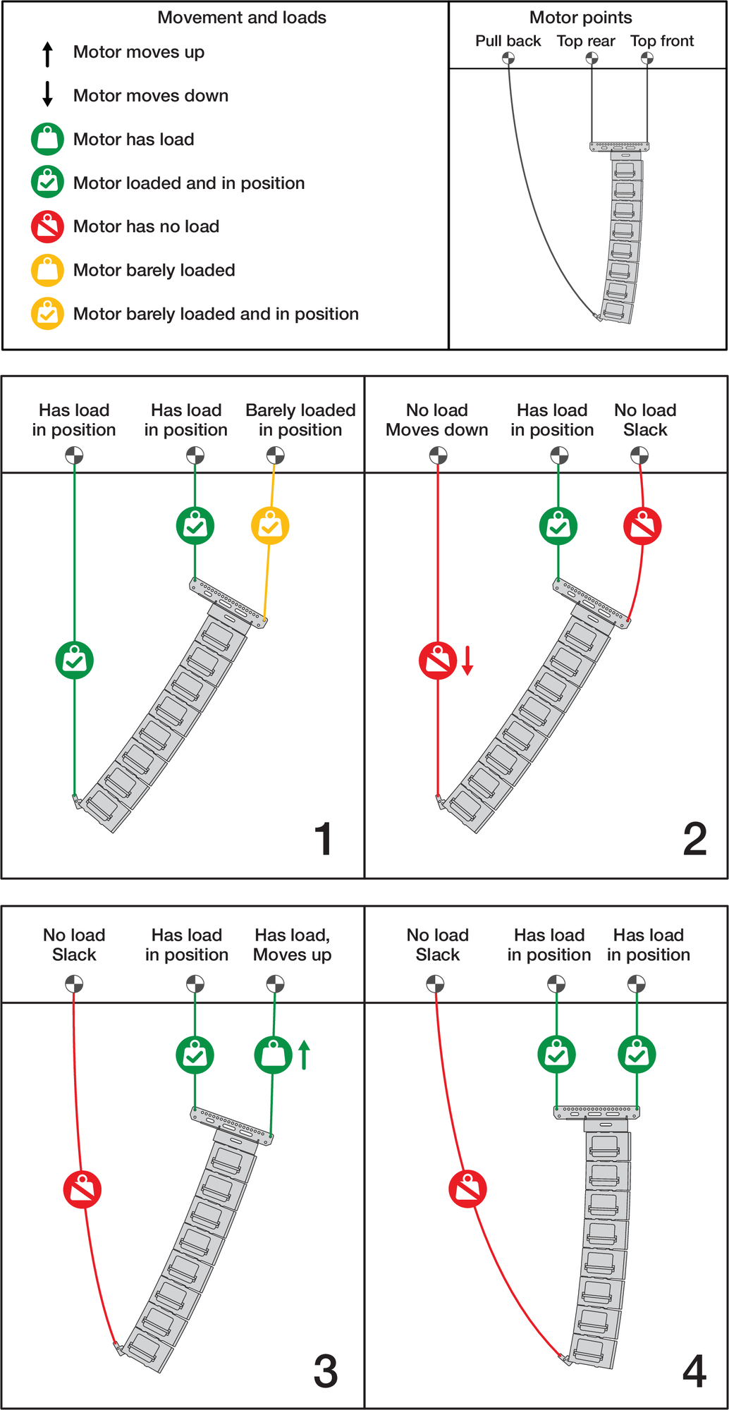
Transition From Pull Back Configuration Steps
When using two hoists connected to the MG-PANTHER Shackle Bar, lower the hoist carrying the greater weight to approximately equalize the weight carried by each hoist.
Lower the array to within 3 ft (1 m) of the working surface and tip the array up, making the bottom cabinet more parallel with the working surface.
Lower the array until the bottom cabinet is 1 to 2 inches (2.5 to 5 cm) above the height of an MCF-PANTHER Caster Frame and move an MCF-PANTHER under the cabinets.
Connect an MCF-PANTHER to the bottom of the array.
Caution
Always lift and pin the rear of the MCF-PANTHER Caster Frame first, then the front. If the front is pinned first and the rear of the caster frame is not supported, the caster frame can swing down, contacting and potentially damaging the PANTHER cabinet.
Remove all four of the quick-release pins from the bottom GuideALink sockets of the PANTHER cabinet.
Caution
When attaching caster frames to cabinets, do not use the handles to lift the caster frame. There is a hand pinch point (see Figure 65). The handles are only intended to be used when lifting or carrying a caster frame not attached to a cabinet.
Lift the rear of the caster frame from the underside of the caster frame.
Seat the rear tabs of the caster frame in the rear GuideALink sockets of the cabinet and insert the previously removed quick-release pins to secure the rear of the caster frame.
Next, lift the front of the caster frame by lifting from the underside of the caster frame.
Seat the front tabs of the caster frame in the front GuideALink sockets of the cabinet and insert the previously removed quick-release pins to secure the front of the caster frame.
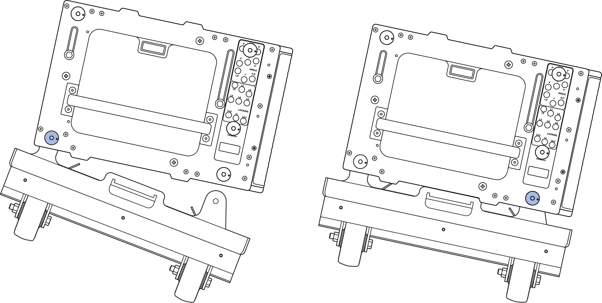
Connect the Rear of the MCF-PANTHER Caster Frame First, Then the Front
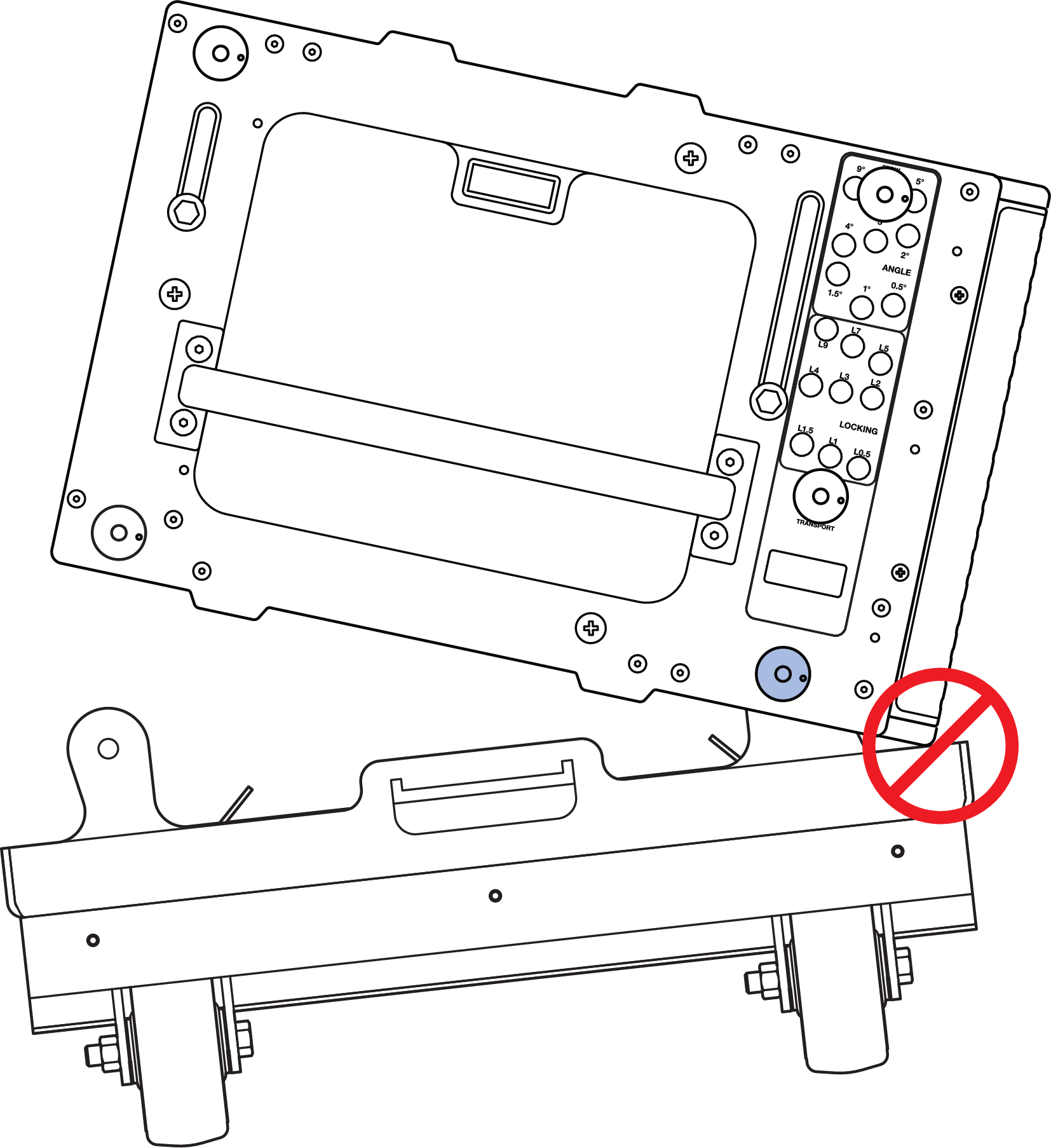
Do Not Connect the Front of the MCF-PANTHER Caster Frame First
Lower the array until the either the front or rear caster frame wheels contact the working surface.
Disconnect all cabling from the cabinets to be removed from the array.
Remove the quick-release pin in the white-on-gray LOCK holes of the cabinets to be disconnected from the array.
Note
Small adjustments of the hoists may be necessary to relieve tension or compression of the front GuideALinks.
Lower the array until the front GuideALinks are no longer extended.
Move the quick-release pins in the gray-on-black ANGLE holes of the cabinets to be disconnected from the array to the STOW / GRID 7° holes.
Remove the quick-release pin securing the rear GuideALink of the top cabinet to be disconnected from the array.
Note
Small adjustments of the hoists may be necessary to relieve tension or compression of the rear GuideALinks. Lower the link and secure with the quick-release pin.
. Remove the Quick Release Pin Securing the Rear GuideALink
Raise the hoists until the quick-release pin securing the front GuideALink can easily be removed.
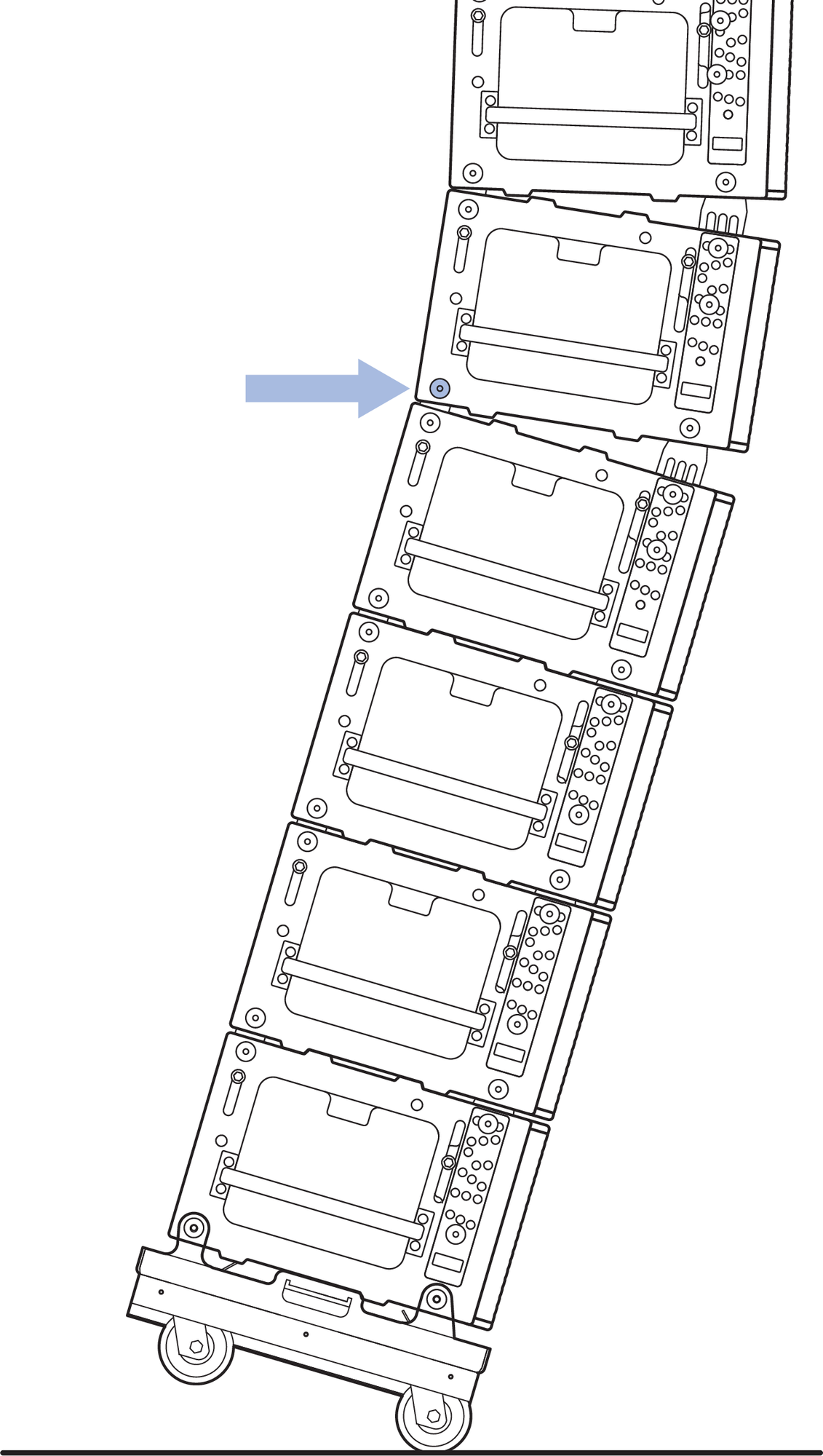
Prepare the stack to be transported.
The quick-release pins can be in any of the gray-on- black ANGLE holes.
For each cabinet, insert a quick-release pin in the white-on-gray LOCK hole labeled 0° GRID / TRANSPORT.
Caution
When PANTHER loudspeakers are stacked in the MCF-PANTHER caster frame, the splay angles should all be 0°. The front and rear GuideALinks of each cabinet should be extended and secured in place with quick-release pins connecting each cabinet of the stack to one another. For stacks that do not include the MG-PANTHER Grid Box, retract the GuideALinks of the top cabinet.
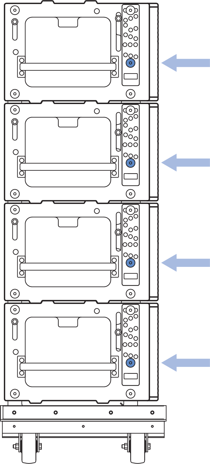
Quick-Release Pins in LOCK Hole Labeled 0° GRID / TRANSPORT.
Move the stack of cabinets from under the suspended array.
Open the flap of the 4-high cover and slide over the top of the stacked cabinets.
Repeat Steps 5-13 for additional stacks of cabinets.
Transporting MG-PANTHER Grid Box on Cabinets
When transporting a MG-PANTHER Grid Box on a stack of cabinets, use the front and rear GuideALinks to secure the MG-PANTHER Grid Box to the top cabinet. This is the same configuration of the GuideALinks as when the array is suspended.
Remove both quick-release pins of the front GuideALink and raise the link into the GuideALink socket of the MG-PANTHER Grid Box.
Insert a pin in the white-on-gray LOCK hole labeled 0° GRID / TRANSPORT and another in the gray-on- black ANGLE hole labeled STOW / GRID 7°.
Insert the 7/16 x 1.50-inch QRP (red button, PN 134.051) quick-release pins included with the MG-PANTHER Grid Box to secure the cabinet to the MG-PANTHER Grid Box.
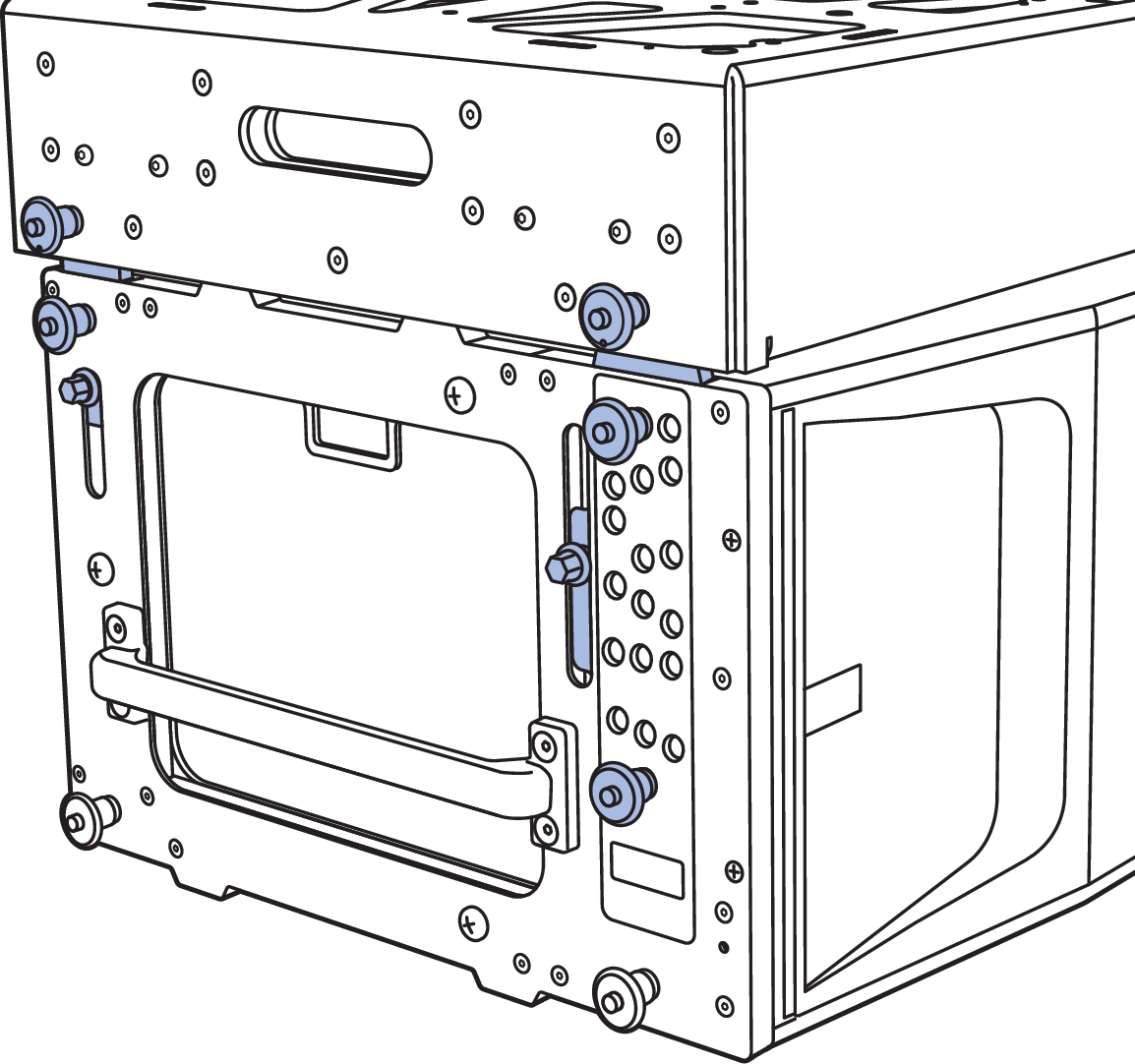
GuideALinks Extended and Secured with Quick-Release Pins
Caution
Do not transport 4-high stacks of PANTHER with the MG-PANTHER Shackle Bar attached to the MG-PANTHER Grid Box. This exceeds the safety limits for tip-over, which may cause injury.
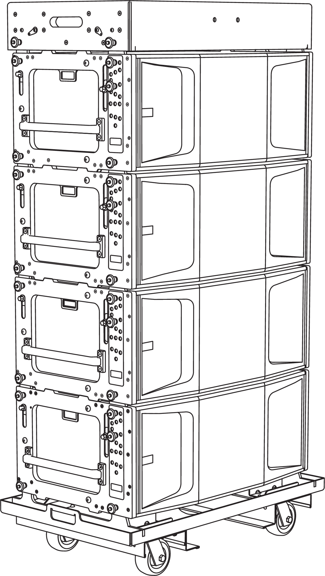 |
MG-PANTHER Shackle Bar Removed, MG-PANTHER Grid Box, PANTHER Cabinets, and MCF-PANTHER Caster Frame