VRAS processing
VRAS processing is used in the Constellation electroacoustic architecture to electronically alter the acoustics of a room. VRAS processing provides two algorithms: reverberation and early reflections.
User interface
VRAS module parameters are controlled from the VRAS window.
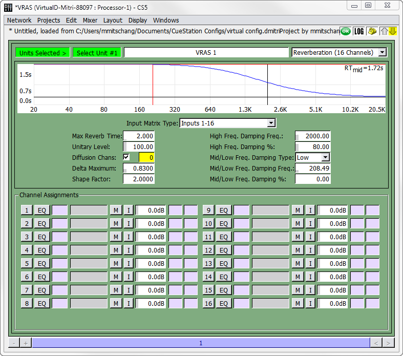 |
VRAS Window
 TIP: When a VRAS module is offline, a message denoting the module’s status now appears at the top of the window.
Global parameters
Global parameters pertain to the current VRAS display.
Parameter | Definition |
|---|---|
Label | The VRAS window shows all current parameter values for each instance of VRAS config- ured in the system. |
Type | Early Reflection, Reverberation (16 Channels), or Reverberation (32 Channels). |
Reverberation parameters (16 or 32 Channels)
Reverberation parameters change the channel assignment, time domain characteristics, and frequency domain characteristics of the reverberation.
Reverberation Parameter | Definition |
|---|---|
Input Matrix Type (16 channel only) | Specifies the input cross-coupling matrix. Selection of this matrix controls the distribution of direct signals from the VRAS inputs to the VRAS outputs. All matrix options maintain the same amount of total power at all outputs. Therefore, while the option Inputs 1-16 can be selected with only input 1 active, this will result in less power output than if the Inputs Channel 1 option is selected. A full table of Input options is provided later in this chapter. |
Max Reverb Time | Adjusts the reverberation time. The Time/Frequency graph near the top provides a visual model of the setting. |
Unitary Level: | Adjusts the unitary property of the reverberator. True unity is set at 100.0, which is recommended for normal operation. As the unitary level is reduced, the amplitude response of the reverberator will vary, gain levels will decrease, and the system will behave more like a con- ventional electronic reverb unit. This can be useful if VRAS is used as an in-line effects reverberator |
# Diffusion Chans | This sets the number of channels to be used as Diffusion Channels. |
Reverberation Parameter | Definition |
|---|---|
Delta Maximum | The higher the delta maximum, the more echo density. However, the amount of direct energy in the reverberator increases proportionately to delta maximum, so there is a trade off between echo density and direct-to-reverberant levels. The Delta Maximum control interacts with the Shape Factor control. When you go outside of the normal operating envelope, the graph in the VRAS Editor will not be drawn. |
Shape Factor | Shape factor is the ratio of the longest to the shortest delay. Low shape factors produce similar internal delay times across channels, while high settings produce a wide spread of delay times. The shape factor also defines how quickly the direct levels drop as the channel numbers rise. A high shape factor will give you a rapid drop in loop gains and direct levels. |
High Freq. Damping Frequency | This is the corner frequency for the reverberator damping. You will see the results of the setting on the Time/Frequency graph. You can simultaneously adjust high frequency damping frequency and amount by clicking and dragging directly in the Time/Frequency graph. |
High Freq. Damping Percentage | This is the amount of damping applied to the reverberator at high fre- quencies (above the damping frequency). You will see the results of the setting on the Time/Frequency graph. |
Mid/Low Freq. Damping Type | VRAS has a second damping filter that can be configured as a mid or low band damping. This control sets the type of the filter. Set to Low if you need low frequency damping to compensate for an excessively boomy room. |
Mid/Low Freq. Damping Frequency | This is the corner frequency for the reverberator damping. You will see the results of the setting on the Time/Frequency graph. |
Mid/Low Freq. Damping Percentage | This is the amount of damping applied to the reverberator at high fre- quencies (above the damping frequency). You will see the results of the setting on the Time/Frequency graph. |
Channel Assignments | This specifies up to 16 inputs to be processed by VRAS Reverbera- tion. For each channel row, there is also a channel label, a mute but- ton, channel attenuation value, and two VGroup assignment boxes. |
The combination of reverb time, delta maximum, and shape factor affect how the hardware memory is allocated and used. Some combinations can exceed the memory capacity of the VRAS DSP, truncating some of the reverberator delays and creating distinct echoes. D-Mitri will warn you with messages in the Log window when you enter values that exceed its mem- ory capacity.
TIP: If you have already calculated the desired delays and attenuations, you can copy and paste in data from the spreadsheet.
Early reflections parameters
These parameters change the channel assignment, time domain characteristics, and fre- quency domain characteristics of the early reflections.
Parameter | Definition |
|---|---|
ER Zone Config | Selects the configuration for early reflections zones. |
Input Matrix | Specifies the input cross-coupling matrix. This matrix controls the distribution of direct signals from the VRAS inputs to the VRAS outputs. A full table of Input options is provided later in this chapter. |
Output Matrix | Specifies the output cross-coupling matrix. Selection of this matrix controls the distribution of user-specified delays to VRAS outputs. Two or four independent ER sub-zones can be specified using appropriate Input and Output Matrix options. For instance, if set to Outputs16 then all 16 delays will be matrixed to all 16 outputs. If set to Outputs 8/8, the first eight delays will be matrixed to the first eight outputs, and the last eight delays to the last eight outputs. |
Cutoff Frequency | Adjusts the cutoff frequency of the included low pass filter applied to VRAS inputs. |
High Frequency Attenuation | Adjusts the amount of attenuation of the high frequencies in the low pass filter. |
Channel Assignments | Specifies up to 16 inputs to be processed by VRAS Early Reflections. For each channel row, there is also a channel label, a mute button, channel attenuation value, and two VGroup assignment boxes. |
Early reflection delays and attenuation
For each early reflection signal, you can configure the delay and attenuation, either by typing in different values, or by dragging the points on the graph.
Parameter | Definition |
|---|---|
Min | Minimum (initial) delay time. |
Max | Maximum (final) delay time. |
Spread | Controls the spread of the early reflections between the minimum and maximum delay times. |
Atten | Controls the range of attenuation levels for each early reflection signal. |
VRAS subcues
There are two VRAS subcue types: VRAS Inputs, which capture channel assignments and attenuations, and VRAS Processing, which captures ER and reverberation settings.
Capturing VRAS Subcues
Like other subcues in the system, VRAS parameters are captured using the Capture window. To capture a VRAS Processing subcue:
In the VRAS window, change the parameters to the desired values.
Channel select the VRAS unit(s) you have configured.
Press the F4 key to open the Capture window, and enter a name for the cue.
Deselect all subcue types, and then click in the checkbox next to VRAS Processing.
Click the Capture New button at the bottom of the window.
When using VRAS Reverberation, you can create a preset that turns VRAS off. One way of doing this is to create a cue that includes a System Level subcue that sets the System Level to -inf dB. However, the reverberant tail will be abruptly cut off. A better way of doing this is to set the attenuation of the inputs to VRAS to -inf dB. This way the existing tail will decay naturally when the cue is recalled and the effect will not be so abrupt. For this effect, you will need to capture a VRAS Inputs subcue:
In the VRAS window, set the input channel attenuations to -inf.
Press the F4 key to open the Capture window, and type in a name for the cue (such as VRAS Off).
Deselect all subcue types, and then click in the checkbox next to VRAS Inputs.
Click the Capture New button at the bottom of the window.
If you create a cue that sets all attenuations to -inf, create another cue that restores the atten- uations (a VRAS On cue). This cue can be created using the same method described above, except that you would set each attenuation to the appropriate level before capturing the cue.