Amplification and Audio
The user panel located on the rear of PANTHER loudspeakers includes audio input connectors, one for analog audio, the other for Milan AVB digital audio.

PANTHER User Panel, Audio Inputs (Sealing Caps Not Shown)
Both audio inputs are always active. If signal is present at both inputs, they are summed and reproduced, which can lead to undesired results. For example, if the Milan and analog input signals are identical for backup purposes, but are not time aligned, comb filtering will occur if both signals are present at the loudspeaker inputs. When using one input as a backup to the other, utilizing the mutes of upstream signal processing is one strategy to switch between input types.
Note
Using Groups and Controls in Compass, a single control button can be assigned to toggle some or all the input or output mutes of a Galileo GALAXY processor or processors.
The analog and Milan inputs will arrive at the loudspeaker at different times due to the transport time of the Milan signal through the network, usually less than 2 ms. The latency of the Milan signal is dependent on the number of network switch hops and the presentation time set in software.
To synchronize the audio reproduction of analog and Milan inputs, measure the acoustic output with an FFT analyzer. Measure and store the phase response when only the Milan input is receiving signal. While only the analog input is receiving signal, add delay to the analog signal processing until both phase responses match.
When one input is used as a backup, synchronizing it with the primary input provides a smoother transition when the signal to the primary input is muted and the backup is unmuted. Synchronizing the inputs also preserves the time alignment with other components of the system, regardless of which input is receiving signal.
Audio Connectors
The user panel includes two 3-pin Neutrik XLR True Outdoor Protection (TOP) connectors for analog audio input and audio loop output. The network connector is a Neutrik etherCON True Outdoor Protection (TOP).
Caution
The analog and network chassis connectors are certified for outdoor protection (IP65, UL50E) only when mated with the Neutrik TOP cable-mount connectors, or the sealing caps are fully inserted.
Check the sealing caps for moisture before covering the connectors. If wet, dry the caps before covering the connectors to avoid introducing liquid into the connectors.
Always seal the connectors with the sealing caps when the connectors are not in use.
Analog Audio Input (XLR 3-Pin Female)
The XLR 3-pin female Input connector accepts balanced audio signals with an input impedance of 10 kOhm. The connector uses the following wiring scheme:
Pin 1 — 1 kOhm to chassis and earth ground (ESD clamped)
Pin 2 — Signal (+)
Pin 3 — Signal (–)
Case — Earth (AC) ground and chassis
Pins 2 and 3 carry the input as a differential signal. Pin 1 is connected to earth through a 1 kOhm, 1000 pF, 15 V clamped network. This circuitry provides a virtual ground lift for audio frequencies while allowing unwanted signals to bleed to ground. Make sure to use balanced XLR audio cables with pins 1, 2, and 3 connected on both ends. Connecting the signal ground at only one end is not recommended. Shorting the signal ground conductor to the connector case may cause a ground loop, resulting in hum
Note
If unwanted noise or hiss is produced by the loudspeaker, disconnect the audio signal cable from the loudspeaker input. If the noise stops, there is most likely nothing wrong with the loudspeaker. To locate the source of the noise, check the audio cable, source audio, AC power, and electrical ground.
Analog Audio Loop Output (XLR 3-Pin Male)
The XLR 3-pin male Loop output connector allows multiple loudspeakers to be looped from a single audio source. The Loop output connector uses the same wiring scheme as the Input connector. For applications that require one drive line to provide signal to multiple PANTHER loudspeakers, connect the Loop output of the first loudspeaker to the Input of the next loudspeaker, and so forth.
Note
The Loop output connector is wired in parallel to the Input connector and transmits the unbuffered source signal even when the loudspeaker is powered off.
Calculating Analog Input Load Impedance
To avoid distortion when looping multiple loudspeakers, make sure the source device can drive the total load impedance of the looped loudspeakers. In addition, the source device must be capable of producing +24 dBU into 50 Ohms to produce the maximum peak SPL over the operating bandwidth of the loudspeaker.
Tip
Audio outputs from Meyer Sound’s Galileo GALAXY Network Platform have an output impedance of 50 ohms. Each output can drive up to 20 Meyer Sound (10 kOhm input) loudspeakers without distortion.
To calculate the load impedance for the looped loudspeakers, divide 10 kOhms (the input impedance for a single loudspeaker) by the number of looped loudspeakers. For example, the load impedance for ten PANTHER loudspeakers is 1 kOhms (10 kOhms / 10). Most source devices are capable of driving loads no less than 10 times their output impedance. To drive this number of looped loudspeakers, the source device should have an output impedance of 100 ohms or less (1000 ohms / 10).
Caution
Make sure all cabling for looped loudspeakers is wired correctly (Pin 1 to Pin 1, Pin 2 to Pin 2, and so forth) to prevent the polarity from being unintentionally reversed. If one or more loudspeakers in a system receive audio signals that are of the opposite polarity, frequency response and coverage will be significantly degraded.
Network Connector
The user panel includes a Milan Endpoint (MEP) module, shown in the figure below, which includes a Neutrik etherCON TOP connector, an Ethernet connectivity LED, an On/Status LED, and a Wink button/LED.

PANTHER User Panel MEP, etherCON TOP Connector
The etherCON TOP connector provides the network connection for transmission of a Milan AVB digital audio signal to the loudspeaker and the transmission of telemetry data from the loudspeaker.
The Milan Endpoint connects to a single channel of a Milan digital audio stream as specified by the Avnu Alliance. To utilize the Milan input, connect the loudspeaker to an Avnu-certified network switch. See avnu.org for the current listing of certified AVB network switches.
The telemetry data of the loudspeaker is also transmitted via this connector, which is displayed in Nebra software. An Avnu-certified switch is not necessary when the network connection is only used to transmit telemetry data. The speed of this network connection is 100 bT, 100 Mb/ second.
Digital Audio Input
When a Milan Endpoint loudspeaker and a computer are connected to the same network via an Avnu-certified network switch, the loudspeaker will be listed in Meyer Sound’s Nebra software where Milan AVB connections are established. The Milan Endpoint loudspeaker must be assigned to an available audio source channel (Talker) as a Listener in order for the loudspeaker to reproduce the audio transmitted by the Talker. The speed of the connection between the last network switch and a Milan Endpoint is 100 bT, 100 Mb/ second. The connection speed between network switches transporting Milan digital audio signals is 1000 bT, 1 Gb/second.
Telemetry
Loudspeakers with Milan Endpoints transmit telemetry data via the network connection. When Milan Endpoint equipped loudspeakers are connected to a computer via a network switch, the loudspeaker telemetry data is displayed in Meyer Sound’s Nebra software.
Tip
Use an Avnu-certified network switch when the Milan digital audio input is used. For a list of Avnu certified AVB switches please refer to the certification pages at avnu.org. When the Milan input is not used, a standard Ethernet network (IEEE 802.3 compliant, supporting at least 100 MB/s, full-duplex) is capable of transmitting the telemetry data.
Nebra software displays system status and performance data for each loudspeaker, including amplifier voltage, limiting activity, power output, fan speed and driver status. A mute function is also available.
Wink Function
The Wink function facilitates the identification of physical loudspeakers that are listed in Meyer Sound’s Nebra software. When routing digital audio signals in software between an output device and a loudspeaker, the loudspeaker name needs to properly indicate which physical loudspeaker will receive the signal.
There are three locations Wink is indicated: Nebra software, the Wink button/LED on the user panel of the loudspeaker, and two LED strips on the front of the PANTHER cabinet.
Once the Milan Endpoint has been discovered in Nebra software, the icons within the loudspeaker’s detail page include a button with an icon of an eye. Double-clicking the icon in Nebra software toggles the Wink function. When the Wink function is active, the Wink button/LED on the user panel of the loudspeaker and the two LED strips on the front of the loudspeaker also illuminate. The Wink function times out after 10 seconds.
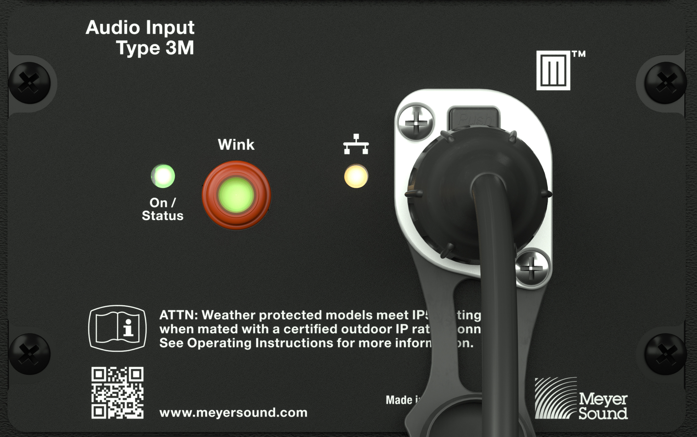
On/Status LED, Wink Button/LED, Network Connectivity LED, and Network Connector.
Wink/Activity LED Button
To activate the Wink function from the loudspeaker, press and hold the Wink button down while observing the On/Status LED, which turns red and then off. Release the Wink button when the On/Status LED turns off, activating the Wink function. The Wink LED turns green for 10 seconds. If the Wink button remains depressed, the On/ Status LED will turn red again and the Wink function will remain off.
To turn off the Wink function, wait 10 seconds for it to time out or depress and hold the Wink button, the On/Status LED will turn red. Wait until the On/Safety LED turns off, then release the Wink button.
Ethernet/Network Connectivity LED
The Ethernet/Network connectivity LED, shown below, is illuminated when a 100 bT link is established; otherwise, it is off.
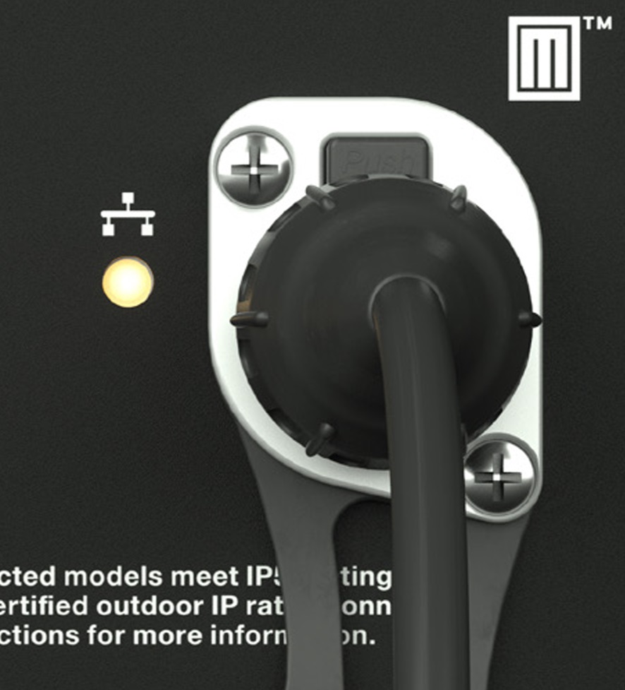 |
On/Status LED, Wink Button/LED, Network Connectivity LED, and Network Connector.
On/Status and Limiting Indication
When powered on, the On/Status LED blinks many times, then turns solid green. During normal operation, the On/Status LED is solid green. If either of the On/Status LEDs blink red after the startup sequence, there is an issue to address. Connect the loudspeaker to a computer running Nebra software to identify the issue.
Limiting activity is indicated when the On/Status LED on the user panel turns from green to yellow, solid yellow for 1 second when the high-frequency channels limit and pulsing yellow when the low-frequency channels limit.
When limiting is engaged, the channel’s gain is reduced. The limiter protects the drivers and prevents signal peaks from causing excessive distortion in the amplifier, thereby preserving headroom and maintaining a smooth frequency response at high levels. When source levels return to normal, below the limiter’s threshold, the LED turns green and limiting ceases.
The loudspeaker performs within its acoustical specifications at normal temperatures when the On/Status LED is green, or when limiting is not continuous. During continuous limiting, the loudspeaker is nearing its operational limits, resulting in the following effects:
Increases to the input level have no effect
Distortion increases due to clipping and nonlinear driver operation.
The drivers are subjected to excessive heat and excursion, which compromises their life span and may eventually damage them.
Caution
The On/Status LED indicates when a safe, optimum level is exceeded. If a PANTHER loudspeaker system begins to limit before reaching the desired acoustic output, consider adding more loudspeakers to the system.
Amplifier Cooling System
PANTHER loudspeakers employ forced-air cooling to prevent overheating. Two variable-speed fans pull air through the vents located on the bottom of the cabinet and below the user panel (see Figure 15). These vents have internal foam to capture any particulate. Most of the air passes over the heat sinks underneath the air cowl. The remainder passes through a fine wire mesh and enters the amplifier module.
Caution
To keep PANTHER from overheating, allow at least six inches (15 cm) of space with unobstructed airflow behind the enclosure for proper ventilation.
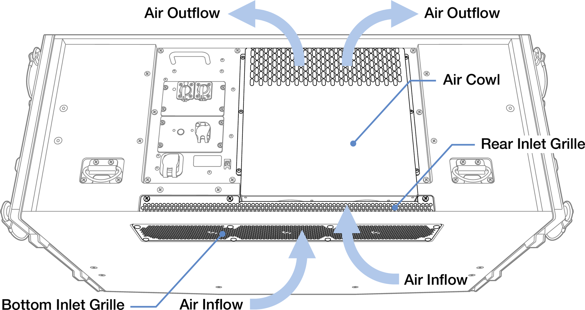
PANTHER Amplifier Ventilation
Caution
Regularly inspect the foam behind the air intake grilles located on the bottom of the cabinet and below the user panel. If a significant amount particulate has accumulated on the foam, remove the intake grilles (not the air cowl covering the heat sinks), then the foam. Vacuum and then rinse the foam with water until the particulate is removed. Allow the foam to dry completely, then reassemble.
Tip
When PANTHER is connected to a network, Meyer Sound’s Nebra software displays telemetry metrics, including the fan status and operating temperature.
Cable Rings
Two cable rings are provided on the rear of the PANTHER cabinet, as shown in the figure below. Power and audio cables should be tied off to these rings to reduce strain and prevent damage to them and the chassis mounted connectors.
Caution
Cable rings should only be used to reduce strain on cables and not be used for any other purpose.

Cables Tied Off to Cable Ring