Assembling Loudspeaker Cables
Caution
When wiring loudspeaker cables, it is extremely important that each pin be wired correctly. Make sure that the 48V DC from the external power supply is wired directly (and only) to the 48V DC pins on the loudspeaker connector, and that the polarity is observed (negative to negative, positive to positive) to avoid damage to the loudspeaker. In addition, make sure that audio pins are wired correctly; polarity reversals for audio signals affect system performance.
Assembling Phoenix-to-Phoenix Loudspeaker Cables
When connecting loudspeakers equipped with Phoenix connectors to the MPS-488HPp power supply, you need a Phoenix 5-pin female to Phoenix 5-pin female cable. The following procedure documents how to assemble this cable.
 |
Assembled Phoenix-to-Phoenix Cable
If the cable has not yet been stripped, strip one end of the cable. Strip the outer shielding by 1 inch and then strip the black, red, blue, and white wires by 0.275 inch.

Insert the five exposed conductors into the five cable holes in a Phoenix 5-pin female cable mount connector. Use the following wiring scheme.

Pin Destinations for Phoenix 5-Pin Female Cable Mount Connector
Secure the conductors by tightening the five screws in the Phoenix cable mount connector. Screws should be torqued to 5–6 Nm(4.4–5.3 In-Lbs).

Caution
Screws should not be inserted into the Phoenix connector while the connector rests in a mating plug. Doing so will damage the contacts. During assembly, the Phoenix connector should only be held in place externally.
Repeat the previous steps and attach the other end of the cable to another Phoenix 5-pin female cable mount connector.
Verify the wiring polarity is correct for both cable ends
Assembling Phoenix-to-EN3 Loudspeaker Cables
When connecting loudspeakers equipped with EN3 connectors to power supplies equipped with Phoenix connectors, a Phoenix 5-pin female to EN3 5-pin female cable is required. The following procedure documents how to assemble this cable. If starting with an EN3-to-pigtail cable, skip steps 4–7 in this procedure.
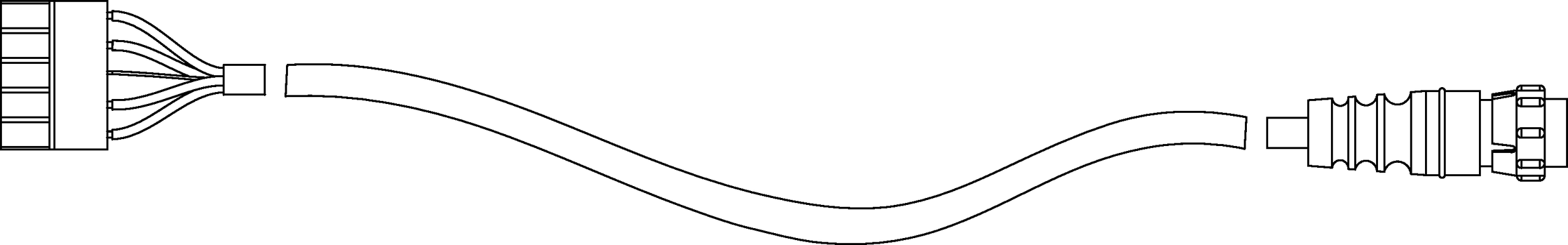 |
Assembled Phoenix-to-EN3 Cable
If the cable has not yet been stripped, strip one end of the cable. Strip the outer shielding by 1 inch and then strip the black, red, blue, and white wires by 0.275 inch.
Insert the five exposed conductors into the five cable holes in a Phoenix 5-pin female cable mount connector. Use the following wiring scheme.
Pin Destinations for Phoenix 5-Pin Female Cable Mount Connector
Secure the conductors by tightening the five screws in the Phoenix cable mount connector. Screws should be torqued to 0.5–0.6Nm (4.4–5.3In-Lbs).
Caution
Screws should not be tightened while the connector rests in a mating plug. Doing so will damage the contacts. During assembly, the Phoenix connector should only be held in place externally.
If the other (EN3) end of the cable has not been stripped, strip the outer shielding 1 inch and then strip the black, red, blue, and white wires 0.275 inch.
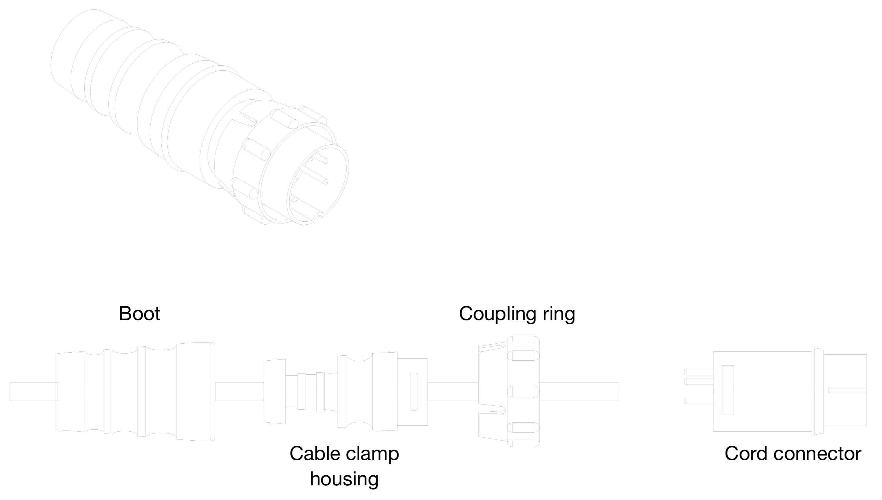
Disassemble the EN3 5-pin female connector and feed the stripped cable through the boot, cable clamp housing, and coupling ring.
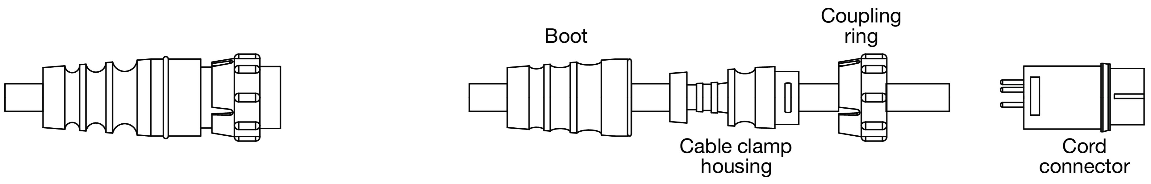
EN3 5-Pin Female Cable Mount Connector, Assembled (Left), Disassembled (Right)
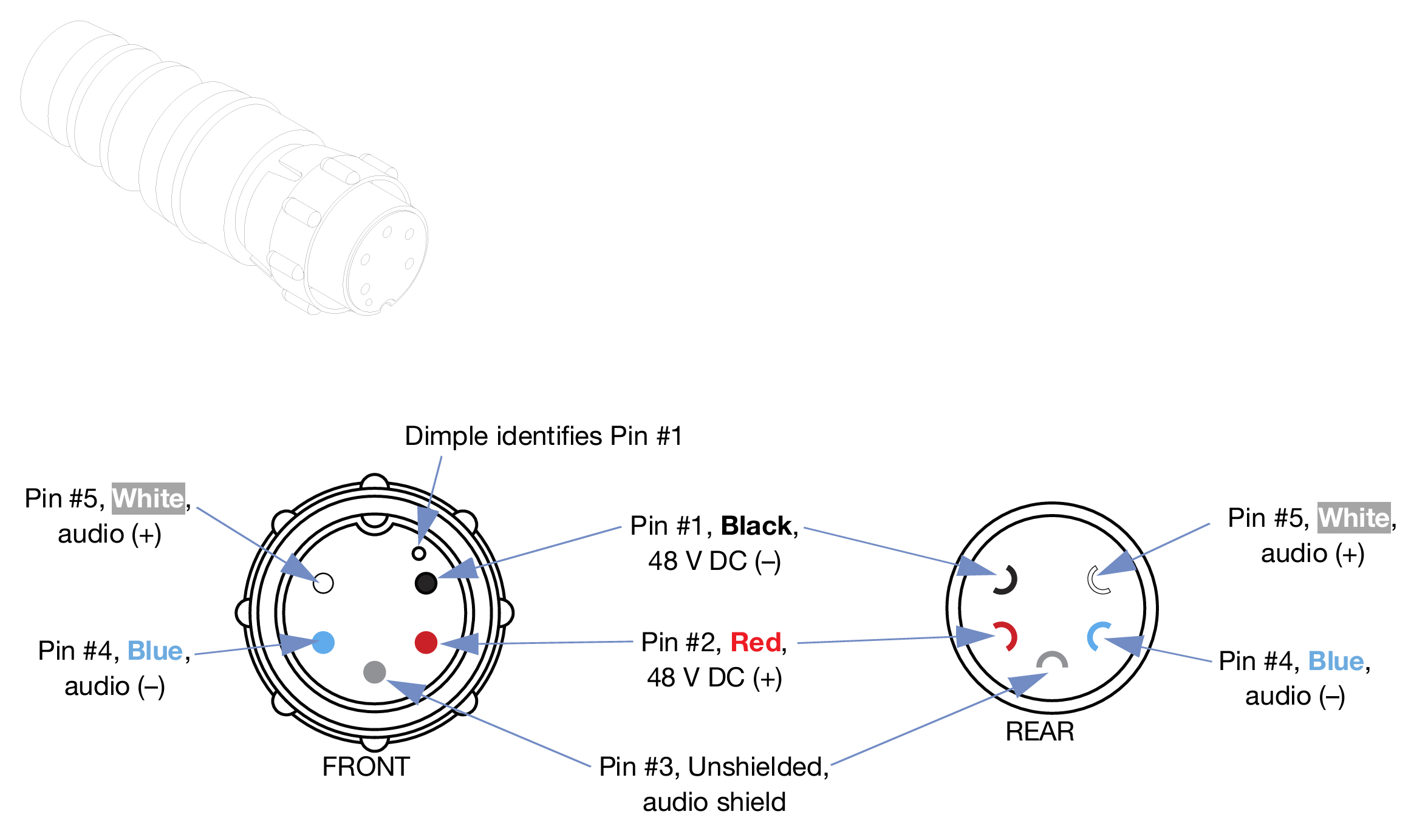
Solder the five exposed conductors to the five pins on the EN3 cord connector using the following wiring scheme.
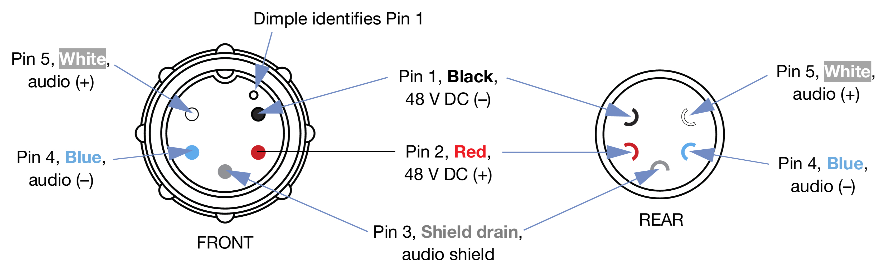
Pin Destinations for EN3 5-Pin Female Cable Mount Connector
Reassemble the EN3 5-pin female connector:
Align the coupling ring’s side notches with the cord connector’s side notches and slide the couple ring onto the cord connector.
Carefully insert the end of the cable clamp housing into the cord connector until it locks into place. Snap the cable clamps in the cable clamp housing into their compartments.
Slide the boot forward so it covers the cable clamp housing completely.
Verify the wiring polarity is correct for both cable ends.
Assembling EN3-to-EN3 Loudspeaker Cables
To connect the MM-4XP loudspeaker directly to the MPS-488E power supply, you need an EN3 5-pin female to EN3 5-pin male cable. The following procedure documents how to assemble this cable. If you are starting with an EN3-to-pigtail cable (included with the MM-4XP), you can disregard step 5 in the procedure.
Note
Cable mount connectors cannot connect to other cable mount connectors. Cable mount connectors can only connect to panel mount connectors (like those on the MM-4XP and MPS-488E) or inline connectors. To extend cables with EN3 connectors on both ends you can use an EN3 5-pin female-to-male cable coupler.
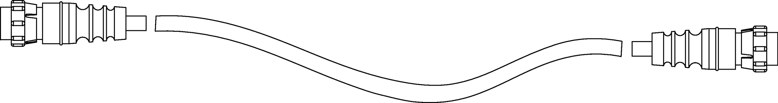 |
Assembled EN3-to-EN3 Cable
If the cable has not yet been stripped, strip one end of the cable. Strip the outer shielding by 1 inch and then strip the black, red, blue, and white wires by 0.275 inch.
EN3 5-Pin Male Cable Mount Connector, Assembled (Left), Disassembled (Right)
Disassemble the EN3 5-pin male connector and feed the stripped cable through the boot, cable clamp housing, and coupling ring.
EN3 5-Pin Male Cable Mount Connector, Assembled (Left), Disassembled (Right)
Solder the five exposed conductors to the five pins on the EN3 cord connector using the following wiring scheme.
Pin Destinations for EN3 5-Pin Male Cable Mount Connector
Reassemble the EN3 5-pin male connector:
Align the coupling ring’s side notches with the cord connector’s side notches and slide the couple ring onto the cord connector.
Carefully insert the end of the cable clamp housing into the cord connector until it locks into place. Snap the cable clamps in the cable clamp housing into their compartments.
Slide the boot forward so it covers the cable clamp housing completely.
Repeat the previous steps to attach the EN3 5-pin female connector to the other end of the cable.
Pin Destinations for EN3 5-Pin Female Cable Mount Connector
Verify the wiring polarity is correct for both cable ends.