Power Requirements
The USW-112P loudspeaker combines advanced loudspeaker technology with equally advanced power capabilities. Understanding power distribution, voltage and current requirements, and electrical safety guidelines is critical for the safe operation of the USW-112P.
AC Power Distribution
All components in an audio system (self-powered loudspeakers, mixing consoles, and processors) must be properly connected to an AC power distribution system, ensuring that AC line polarity is preserved and that all grounding points are connected to a single node or common point using the same cable gauge (or larger) as the neutral and line cables.
Caution
Make sure the voltage received by the USW-112P loudspeaker remains within its 90–264 V AC operating range. In addition, the ground line must always be used for safety reasons and the line-to-ground voltage should never exceed 250 V AC (typically 120 V AC from line to ground).
Before applying AC power to any Meyer Sound self-powered loudspeaker, make sure that the voltage potential difference between the neutral and earth-ground lines is less than 5 V AC when using single-phase AC wiring.
Note
Improper grounding of connections between loudspeakers and the rest of the audio system may produce noise or hum, or cause serious damage to the input and output stages of the system’s electronic components.
120V AC, 3-Phase Wye System (Single Line)
Line-Neutral-Earth/Ground
The figure below illustrates a basic 120 V AC, 3-phase Wye distribution system with the loudspeaker load distributed across all three phases and with each loudspeaker connected to a single line and common neutral and earth/ground lines. This system delivers 120 V AC to each loudspeaker.

120 V AC, 3-Phase Wye System (Single Line to Loudspeakers)
120V AC, 3-Phase Wye System (Two Lines)
Line-Line-Earth/Ground
The figure below illustrates a 120 V AC, 3-phase Wye distribution system with each loudspeaker connected to two lines and a common earth/ground line. This configuration is possible because the UPQ-D Series tolerate elevated voltages from the ground line and does not require a neutral line. This system delivers 208 V AC to each loudspeaker.
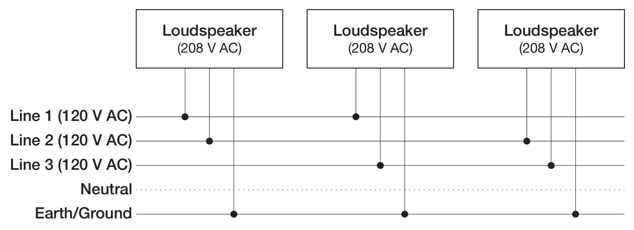
120 V AC, 3-Phase Wye System (Two Lines to Loudspeakers)
Tip
The 120 V AC, 3-phase Wye system with two lines is recommended because it allows loudspeakers to draw less current than with single-line systems, thereby reducing voltage drop due to cable resistance. It also excludes the potential of varying ground to neutral voltages producing an audible hum.
230V AC, 3-Phase Wye System (Single Line)
Line-Neutral-Earth/Ground
Figure 5 illustrates a basic 230 V AC, 3-phase Wye distribution system with the loudspeaker load distributed across all three phases and with each loudspeaker connected to a single line and common neutral and earth/ ground lines. This system delivers 230 V AC to each loudspeaker.

230 V AC, 3-Phase Wye System (Single Line to Loudspeakers)
Caution
For 230 V AC, 3-phase Wye systems, never connect two lines to the AC input of a UPQ-D Series loudspeaker, as the resulting voltage would exceed the upper voltage limit (275 V AC) and will damage the loudspeaker.
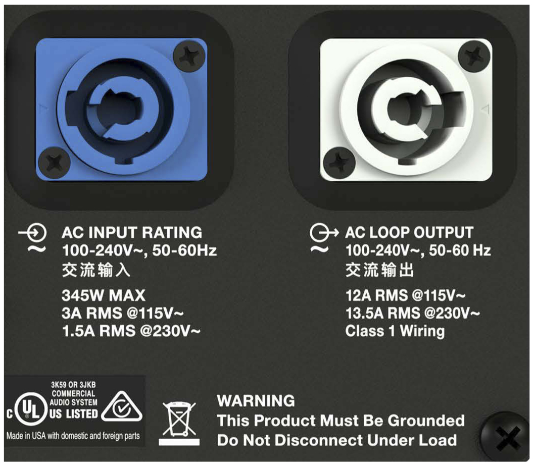
AC Connectors
The USW-112P user panel includes two powerCON 20 connectors, as shown in the figure below, one for AC Input (blue) and one for AC Loop Output (gray).
AC Input (Left) and AC Loop Output (Right) Connectors
The weather-protected and digital versions use the robust PowerCON TRUE1 TOP chassis connector shown in the figure below.
Caution
The PowerCON TRUE1 TOP chassis connectors are certified for outdoor protection only when used in combination with PowerCON True1 TOP cable connectors or with the sealing cap in place when the chassis connectors are not in use.
Ensure the rubber sealing cover is in place when either connector (input or loop) is not in use.
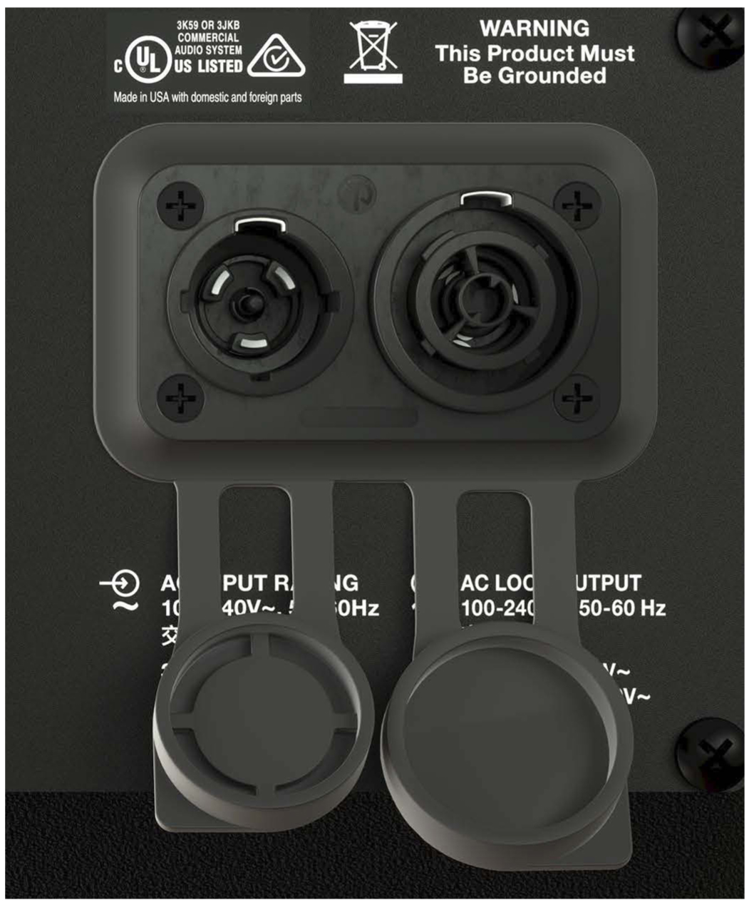
PowerCON TRUE1 TOP Connector Panel (Covers Open)
AC Input (Blue)
The blue AC Input connector supplies power to USW-112P. The 3-conductor powerCON 20 is rated at 20 A and uses a locking connector that prevents accidental disconnections. A 10-foot AC power cable, rated at 15 A, is included with each loudspeaker. If the included AC power cable is replaced, make sure to use a cable with the appropriate power plug (on the other end) for the region where the unit will be operated. USW-112P requires a grounded outlet. To operate safely and effectively, it is extremely important that the entire system be properly grounded.
The AC Input connector also supplies power to any additional loudspeakers connected to the loudspeaker’s gray Loop Output connector.
Caution
When looping AC power for loudspeakers, do not exceed the current capability of the AC Input connector (20 A) or the included AC power cable (15 A). Consider the total current draw for all loudspeakers on the circuit, including the first loudspeaker.
AC Loop Output (Gray)
The gray AC Loop Output connector allows multiple USW-112P to be looped and powered from a single power source. The 3-conductor powerCON 20 is rated at 20 A and uses a locking connector that prevents accidental disconnections. For applications that require multiple USW-112P, connect the AC Loop Output of the first loudspeaker to the AC Input of the second loudspeaker, and so forth.
The maximum number of loudspeakers that can be looped from the AC Loop Output connector is determined by the voltage of the power source, the current draw of the looped loudspeakers, the circuit breaker rating, and the rating of the AC power cable connected to the first USW-112P loudspeaker, as described in the table below.
Circuit Breaker/ Connector Rating | 115 V AC | 230 V AC | 100 V AC |
|---|---|---|---|
15 A | 10 looped (11 total) | 18 looped (19 total) | 8 looped (9 total) |
20 A | 14 looped (15 total) | The | 11 looped (12 total) |
Note
Current draw for USW-112P is dynamic and fluctuates as operating levels change. The indicated number of loudspeakers that can be looped assumes that operating levels are normal and not such that loudspeakers are constantly limiting.
USW-112P ships with a gray powerCON 20 cable mount connector, rated at 20 A, for assembling AC looping cables. Assembled 1-meter AC looping cables are also available from Meyer Sound.
Wiring AC Power Cables
USW-112P ships with a gray powerCON 20 cable mount connector, rated at 20 A, for assembling AC looping cables, as shown in the figure below. The pins on the powerCON 20 cable mount connector are labeled as follows:
L (Line)
N (Neutral)
PE (Protective Earth or Ground)
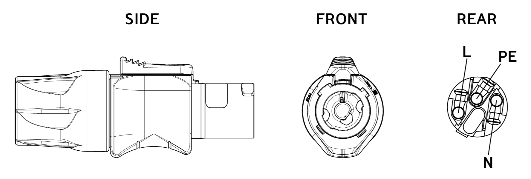
powerCON 20 Cable Mount Connector
How AC power cables are wired is determined by the type of AC power distribution system used (see “AC Power Distribution” on page 5). When wiring AC power cables for single-line systems, use one of the wiring schemes shown in the figure below and described in the table below:
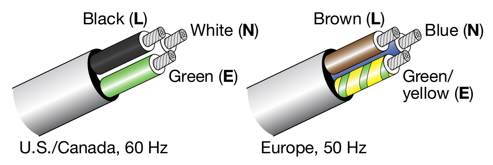 |
AC Wiring Scheme
Wire Color | Attach to the Following Terminal | |
|---|---|---|
U.S. /Canada 60 Hz | European 50 Hz | |
Black | Brown | Hot or live (L) |
White | Blue | Neutral (N) |
Green | Green and Yellow | Protective earth / ground (E or PE) |
Caution
When wiring AC power cables and distribution systems, it is important to preserve AC line polarity and connect the earth ground at both ends of the cable. USW-112P requires a grounded connection. Always use a grounded outlet and plug. It is extremely important that the system be properly grounded to operate safely and properly. Do not ground-lift the AC cable.
Voltage Requirements
USW-112P operates as intended when receiving AC voltage within the following range:
90–264 V AC, 50–60 Hz
If the voltage drops below 90 V, the loudspeaker uses stored power to continue operating temporarily; the loudspeaker powers off if the voltage does not return to its operating range.
If the voltage rises above 275 V, the power supply could become damaged.
Caution
The power source for the USW-112P should always operate within the required operating range, at least a few volts from the upper and lower limits. This approach ensures that AC voltage variations from the service entry—or peak voltage drops due to cable runs—will not cause the loudspeaker’s amplifier to cycle on and off or cause damage to the power supply.
Current Requirements
Current draw for loudspeakers is dynamic and fluctuates as operating levels change. Because different cables and circuit breakers heat up at varying rates, it is important to understand the following types of current ratings and how they affect circuit breaker and cable specifications.
Idle Current — The maximum rms current during idle periods.
Maximum Long-Term Continuous Current — The maximum rms current during a period of at least 10 seconds. The maximum long-term continuous current is used to calculate temperature increases for cables and to ensure that the size and gauge of each cable conforms to electrical code standards. This current rating is also used to select appropriately rated, slow-reacting thermal breakers, which are recommended for loudspeaker power distribution. In addition, the maximum long-term continuous current can be used to calculate the AC looping capability for USW-112P loudspeakers.
Burst Current — The maximum rms current during a period of around 1 second. The burst current is used as a rating for magnetic breakers. It is also used for calculating the peak voltage drop in long AC cable runs according to the following formula:
V pk (drop) = I pk x R (cable total)
Maximum Instantaneous Peak Current — A rating for fast-reacting magnetic breakers.
Use the information in the table below to select the appropriate cable gauge and circuit breaker ratings for the system’s operating voltage.
Current Draw | 115 V AC | 230 V AC | 100 V AC |
|---|---|---|---|
Idle | 0.23 A rms | 0.18 A rms | 0.25 A rms |
Maximum Long-Term Continuous | 1.2 A rms | 0.7 A rms | 1.4 A rms |
Burst | 3.6 A rms | 1.8 A rms | 4.1 A rms |
Maximum Instantaneous Peak | 8.9 A peak | 4.5 A peak | 10.3 A peak |
The minimum electrical service amperage required by a loudspeaker system is the sum of the maximum long-term continuous current for all loudspeakers. An additional 30 percent above the combined Maximum Long-Term Continuous amperages is recommended to prevent peak voltage drops at the service entry.
Note
For best performance, the AC cable voltage drop should not exceed 10 V (10 percent at 115 V and 5 percent at 230 V). This approach ensures that the AC voltage variations from the service entry—or peak voltage drops due to longer cable runs—do not cause the amplifier to cycle on and off.
Intellegent AC Power Supply
USW-112P’s Intelligent AC™ power supply automatically selects the correct operating voltage (allowing the loudspeaker to be used internationally without manually setting voltage switches), eliminates high inrush currents with soft-start power up, suppresses high-voltage transients up to several kilovolts, filters common mode and differential mode radio frequencies (EMI), and sustains operation temporarily during low-voltage periods.
Powering on USW-112P
When powering on USW-112P, the following startup events take place over several seconds.
Audio output is muted.
Voltage is detected and the power supply mode is automatically adjusted as necessary.
The power supply ramps up.
On the user panel, the Limit and On/Status LED flashes multiple colors successively.
The Limit and On/Status LED turns solid green, indicating the loudspeaker is unmuted and ready to output audio.
Caution
If the Limit and On/Status LED does not turn solid green, or the USW-112P does not output audio after 10 seconds, remove AC power immediately and verify that the voltage is within the required range. If the problem persists, contact Meyer Sound Technical Support.
Electrical Safety Guidelines
Make sure to observe the following important electrical and safety guidelines.
The powerCON 20 connector should not be engaged or disengaged when under load or energized. Either de-energize or disconnect the other end of the cable.
USW-112P requires a grounded outlet. Always use a grounded outlet and plug.

Do not use a ground-lifting adapter or cut the AC cable ground pin.

Do not exceed the current capability of the 20 A AC Input connector for the loudspeaker. When looping loudspeakers, consider the total current draw for all loudspeakers on the circuit, including the first loudspeaker.
Make sure the AC power cable for the loudspeaker has the appropriate power plug (on the other end) for the area in which you will operate the loudspeaker. In addition, the AC power cable must be rated for the total current draw of all loudspeakers looped from the power source.
Do not operate the unit if the power cable is frayed or broken.
Keep all liquids away from USW-112P loudspeakers to avoid hazards from electrical shock.