Datasheet — CAL™ (Legacy)
Column Array Loudspeaker

 |
 |
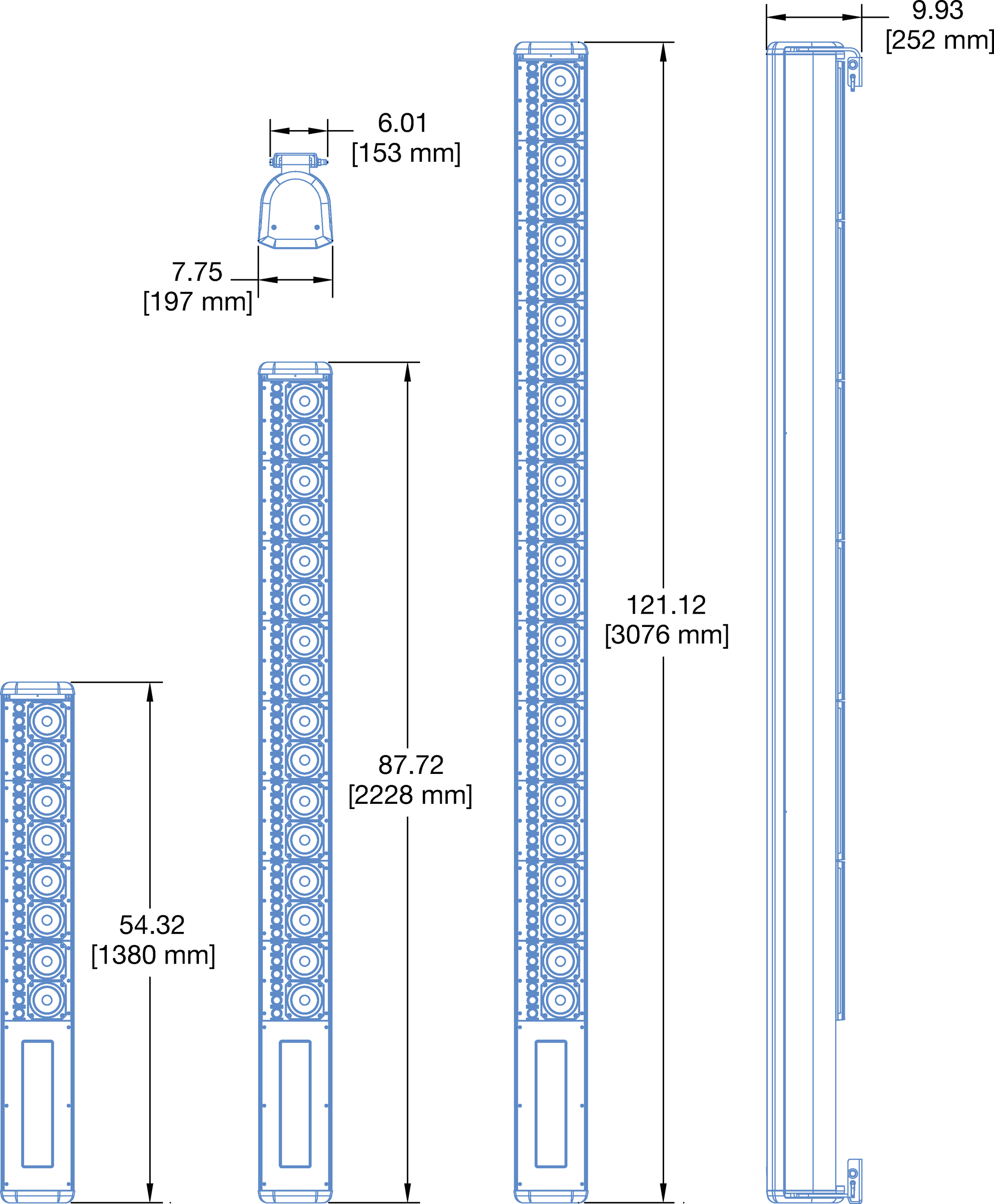 |
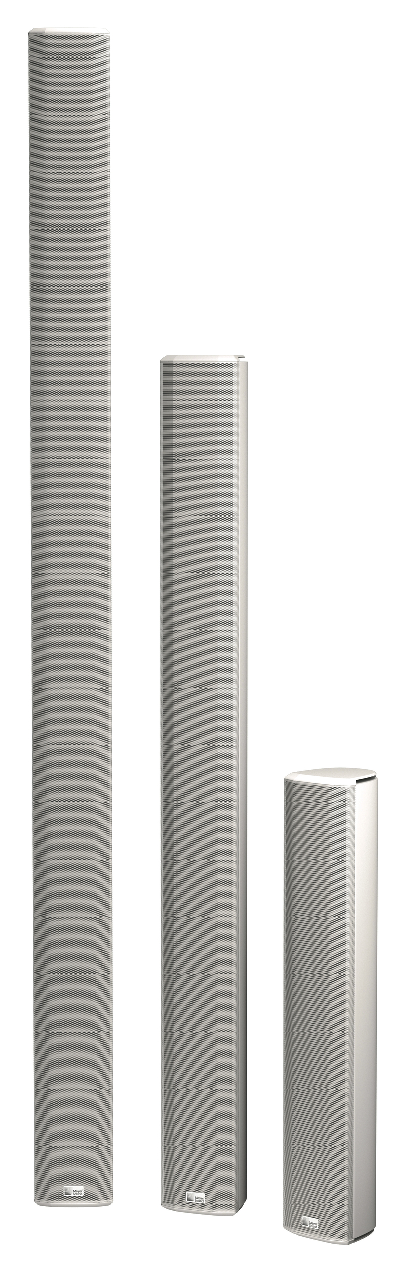
CAL Loudspeakers and Dimensions
The CAL steerable column array loudspeaker incorporates over three decades of technological innovation and advanced research to achieve unprecedented accuracy in sound reproduction. The first loudspeaker to be certified for AVB interoperability by the Avnu Alliance®, the self-powered CAL is designed primarily for vocal reproduction in fixed installations. It offers variable vertical beam spread (as narrow as 5° and as wide as 30° in 5° increments) that can be digitally steered up or down by 30° (in 1° increments). CAL’s beam steering takes the practice of directing sound to the next level, and with a smart, lean profile, CAL sets the standard for high-quality sound installations.
CAL is available in three models, each providing a different output level—up to a linear peak SPL of 101 dB with 18.5 dB crest factor (measured using M-noise4) for CAL 96 at 90 m—over an operating frequency range of 100 Hz to 16 kHz. Providing a horizontal coverage of 120°, as well as the flexibility of vertical beam steering, a single unobtrusive CAL delivers clear vocal reproduction over a large area while minimizing undesirable reflections.
Discrete onboard class D amplifier channels, processed by sophisticated algorithms, power each driver and tweeter. The amplitude and phase response of each driver are engineered to produce interactions that yield the desired vertical spread.
Controlling each element individually yields greater flexibility and precision than other beam steering systems that control modules consisting of multiple drivers.
The accuracy of CAL’s vertical steering allows system designers to pinpoint coverage, even when mounting options in a venue do not allow for physically aiming a loudspeaker toward a coverage area. CAL 96 and CAL 64 include split beams that can be configured to fit the application, for example, to avoid hitting a reflective balcony surface. To meet the high intelligibility requirement for vocal reproduction, CAL maintains accurate beam steering up to 10 kHz, well beyond the benchmark of 4 kHz used in traditional single-driver loudspeakers.
CAL loudspeakers include AVB-enabled Ethernet ports that accept AVB audio streams as source signals, and also provide computer control of CAL via Meyer Sound’s Compass control software which allows beam control and RMS™ real-time monitoring of each loudspeaker on the network.
CAL comes standard with adjustable mounting brackets for installation on walls or columns. The low-profile aluminum enclosure is available in white, black, and custom colors, allowing it to blend easily into any background. Weather protection permits outdoor installations in most environments.
Features and Benefits
Variable vertical spread from 5° to 30° in 5° increments
60° of vertical beam steering, ±30° in 1° increments
Proprietary drivers optimized for high output and low distortion
Discrete amplifier channels and signal processing for each driver and tweeter
AVB-enabled Ethernet ports for audio streaming and computer control
Compass control software provides control of CAL beam configurations
Low profile enclosure and custom colors blend into any environment
Weather protection and rain hood included for outdoor installations
First Avnu®-certified loudspeaker
Applications
Airports
Convention centers
Stadiums
Places of worship
Shopping malls and retail spaces
Reverberant spaces requiring low-profile sound reinforcement for voice
Accessories and Associated Products
CAL Single Point Hang Kit — The Single Point Hang Kit includes a bracket, eye bolt, and loudspeaker attachment hardware to facilitate hanging of a CAL loudspeaker instead of mounting.
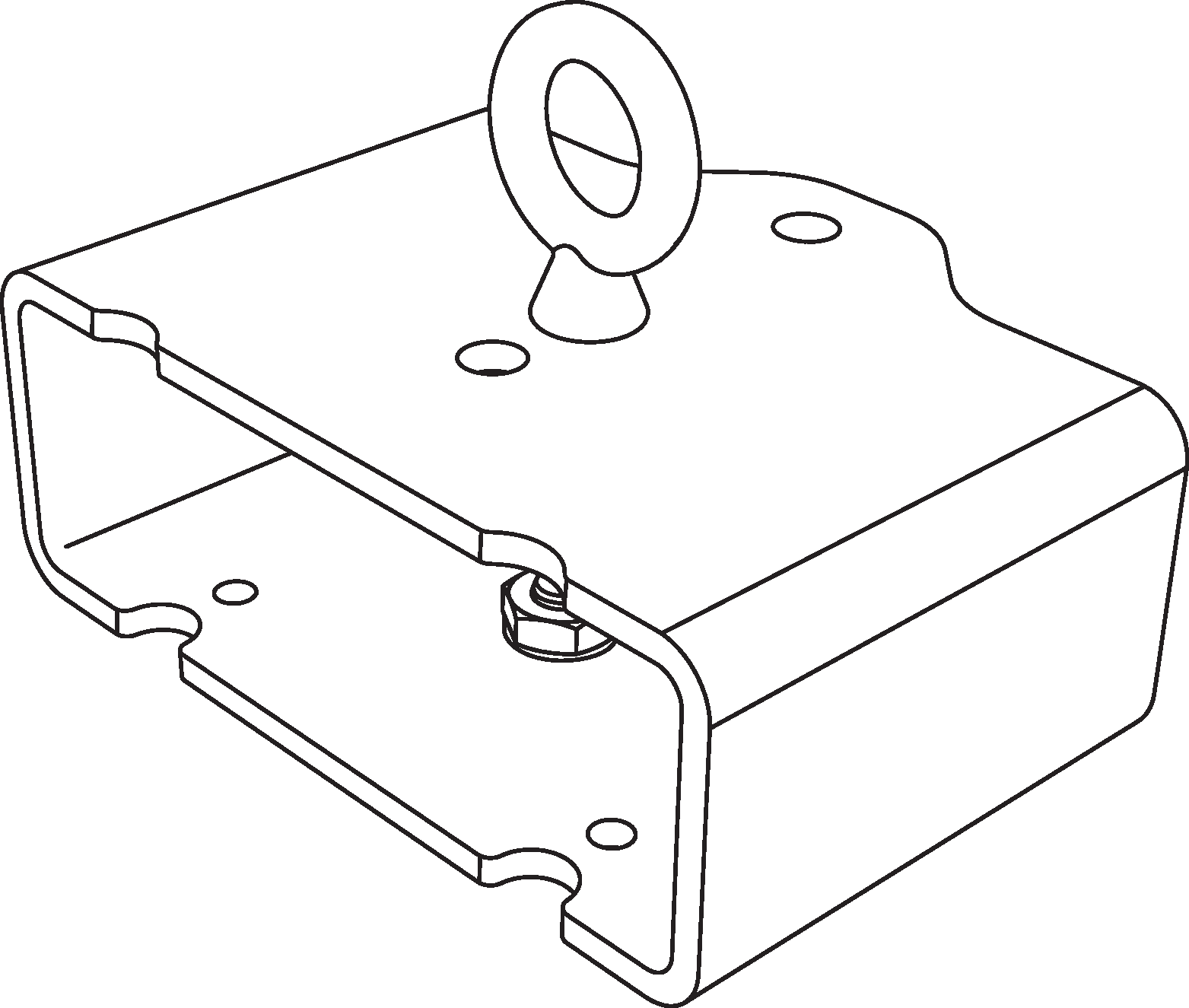 |
CAL Single Point Hang Kit
Variable Vertical Spread and Beam Steering
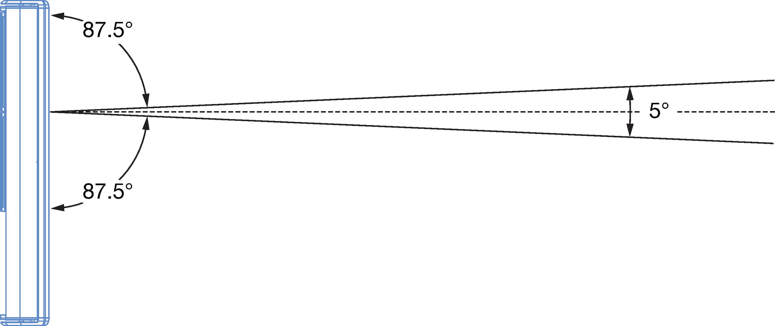
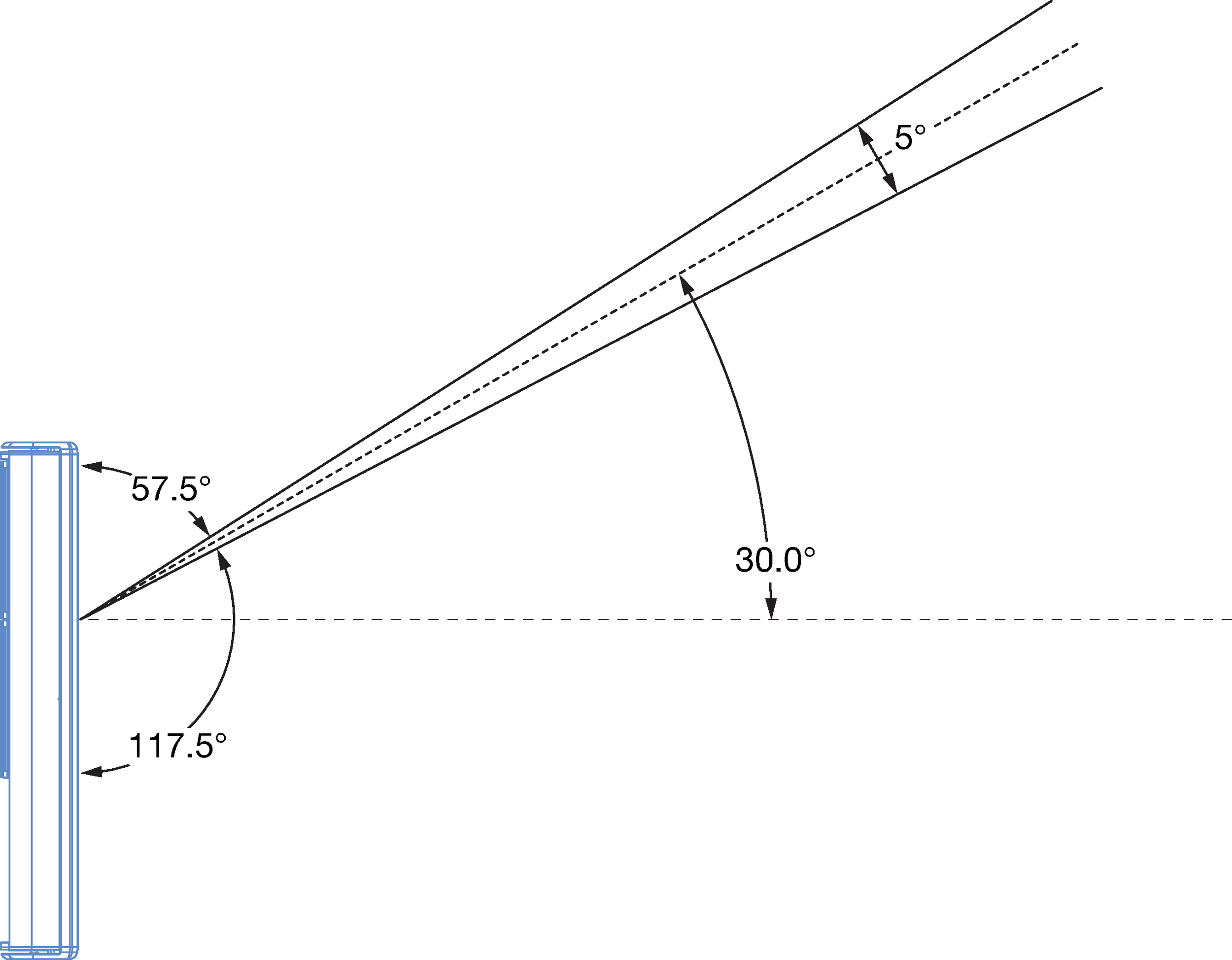
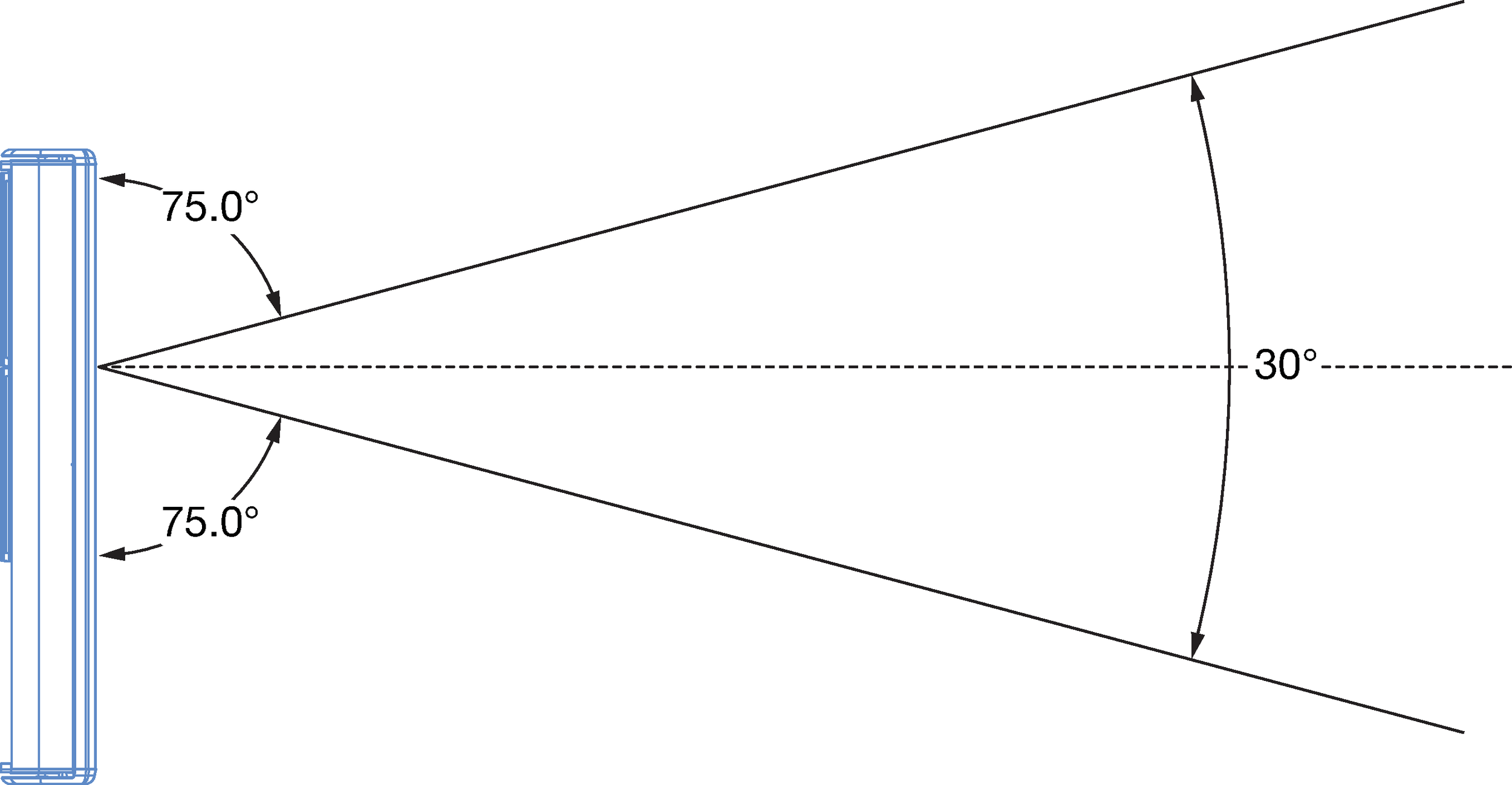
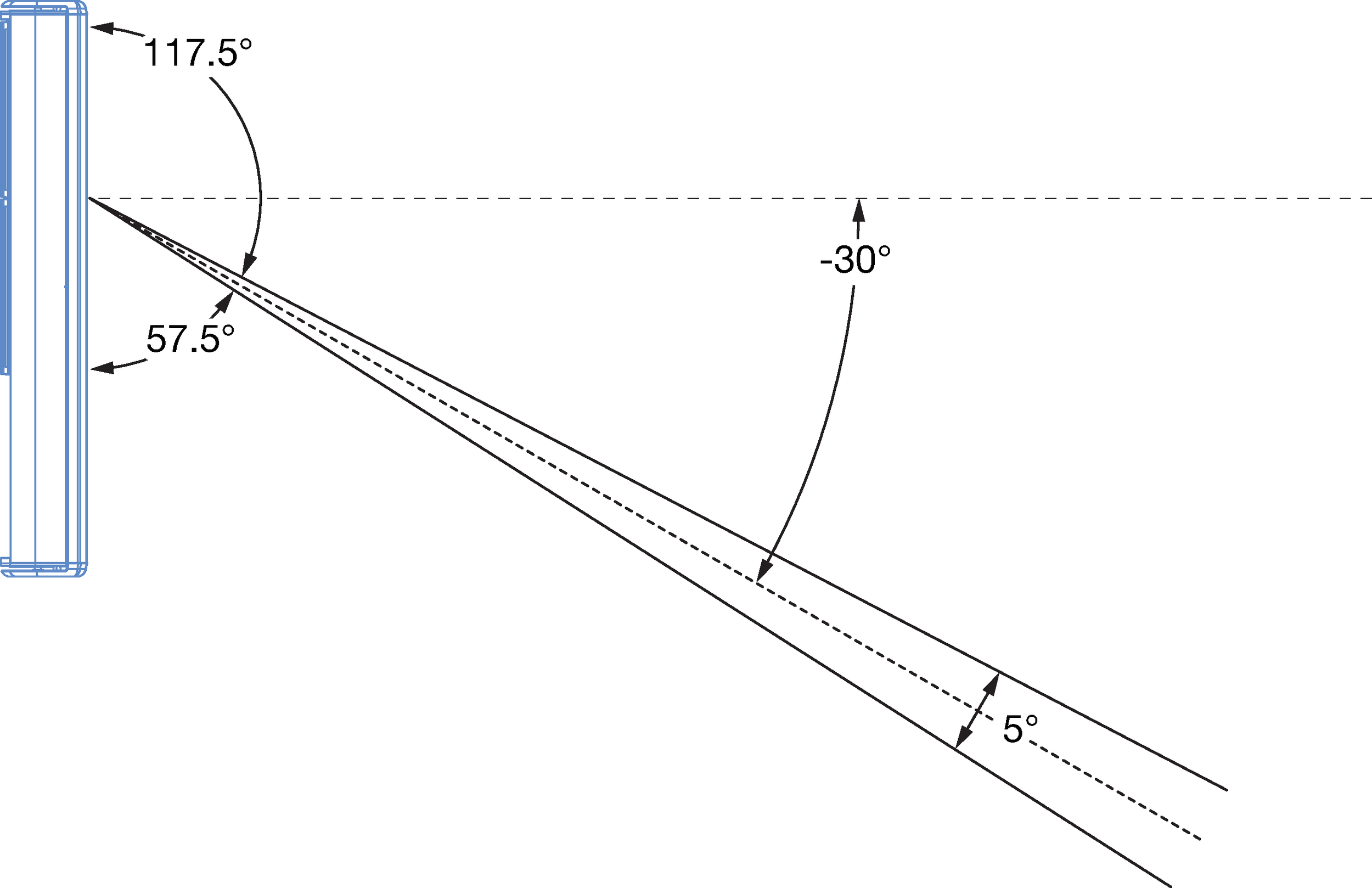
CAL loudspeakers provide vertical beams with variable spread from 5° to 30° in 5° increments. The vertical beams can also be steered ±30° in 1° increments.
CAL 32, 5°Beam |
CAL 32, Beam Steered +30° | ||
CAL 32, 30°Beam |
CAL 32, Beam Steered –30° |
Vertical Beam Splits
CAL 96 and CAL 64 provide split beam coverages to aim sound toward two destinations or to avoid reflective surfaces such as a balcony. The vertical spread and steering of the split beams can also be configured.
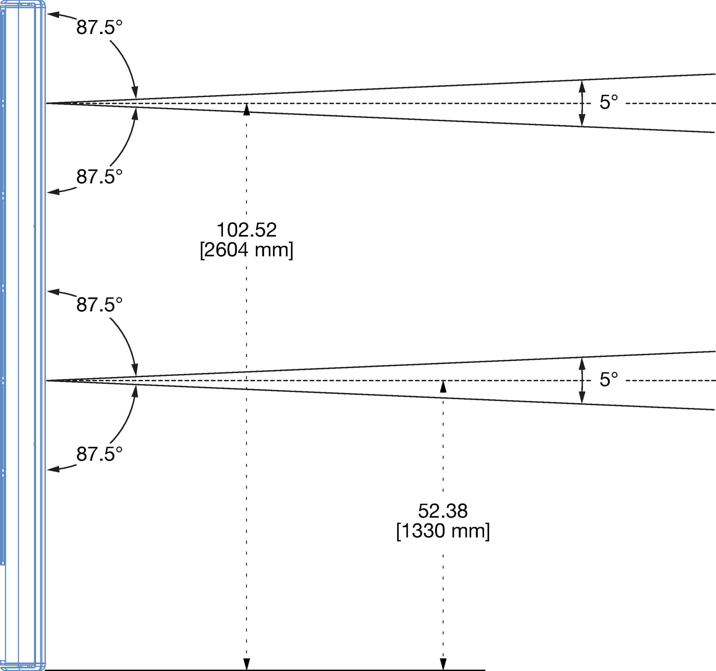 |
CAL 96, Top Split Beam Coverage
Compass Control Software
Compass control software provides comprehensive control of CAL through a graphical user interface. The software enables easy access to all CAL features and even provides control of multiple units. Compass runs on a Mac® or Windows®-based computer.
With Compass, users can set the active input and override input; configure vertical beam spread, beam steering, and beam splits; assign processing to beams, including gain, delay, and parametric EQ; edit, store, recall, and organize CAL presets; test logic I/O, including input mute, input override, fault, contact, and preset selection, and monitor loudspeaker system status and performance data from the RMS tab.
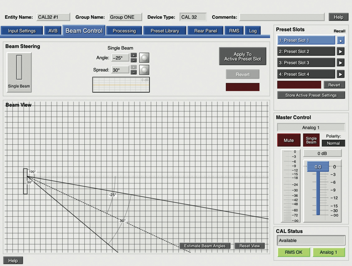 |
The Beam Control tab displays CAL’s vertical beam spread and vertical steering, both of which can be altered by entering angle values or by dragging in the beam view area. Split beams can also be configured on the Beam Control tab (CAL 64 and CAL 96 only).
Specifications
ACOUSTICAL1 | ||||
Operating Frequency Range2 | 100 Hz – 16 kHz | |||
Frequency Response3 | 105 Hz – 15 kHz ±4 dB | |||
Phase Response | 230 Hz – 16.9 kHz ±45° | |||
Linear Peak SPL4 | CAL 96 at 90 m (295 ft), CAL 64 at 60 m (196 ft), CAL 32 at 30 m (98 ft): 101 dB with 18.5 dB crest factor (M-noise), 98 dB (Pink noise), 100 dB (B-noise) | |||
COVERAGE | ||||
Horizontal Coverage | 120° | |||
Vertical Coverage | Variable, 5° to 30° in 5° increments | |||
Vertical Steering | ±30° in 1° increments | |||
Vertical Beam Splits | CAL 96: Top split, bottom split CAL 64: Center split CAL 32: None | |||
TRANSDUCERS | ||||
Low Frequency | CAL 96: (24) 4-inch cone drivers CAL 64: (16) 4-inch cone drivers CAL 32: (8) 4-inch cone drivers | |||
High Frequency | CAL 96: (72) 20 mm tweeters CAL 64: (48) 20 mm tweeters CAL 32: (24) 20 mm tweeters | |||
AMPLIFIER | ||||
Type | Multichannel class D, one channel per driver | |||
Number of Channels | 96 (CAL 96); 64 (CAL 64); 32 (CAL 32) | |||
Cooling | Convection and forced air | |||
AUDIO/CONTROL | ||||
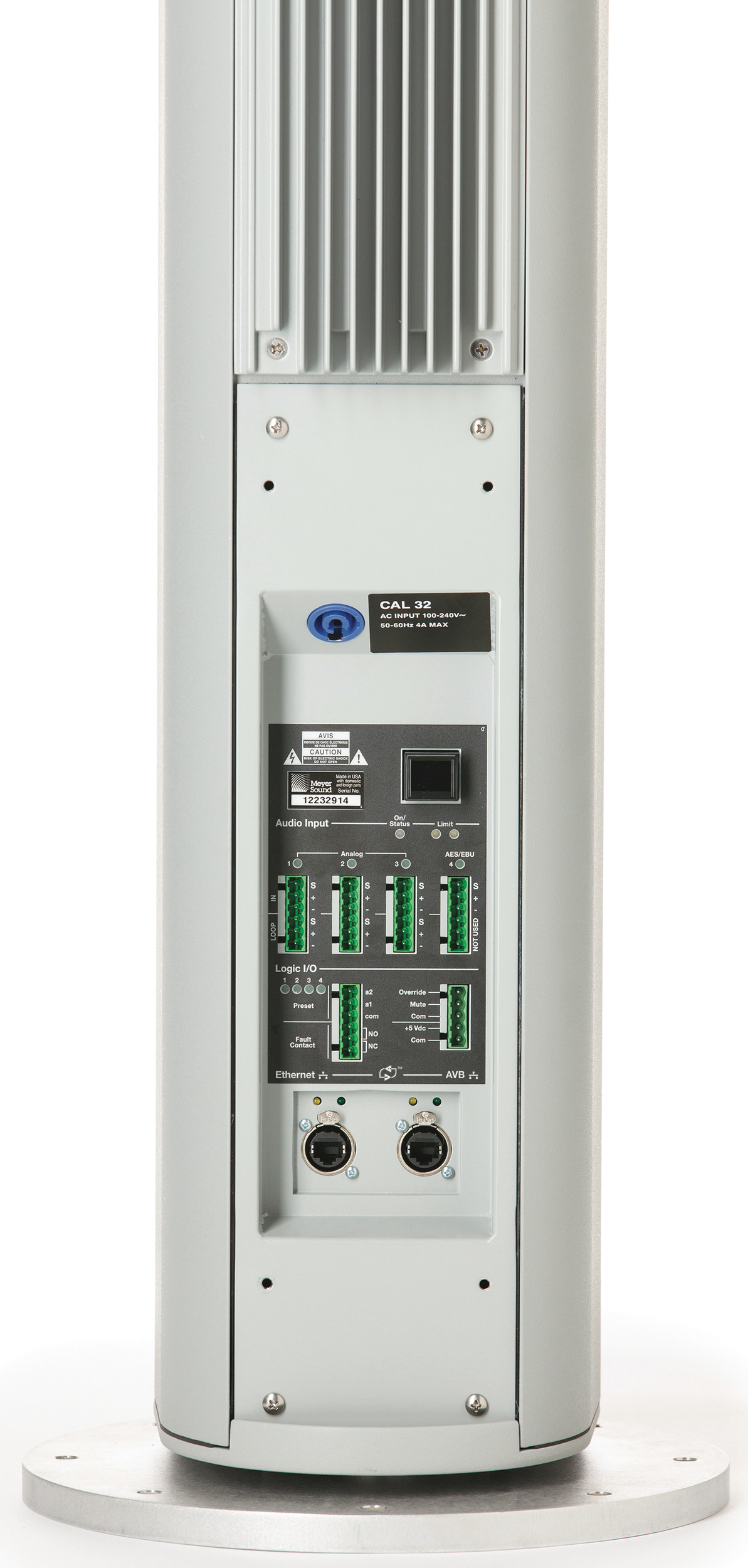
Analog Audio | (3) Phoenix 6-pin male connectors for balanced audio input and loop output | |||
Digital Audio5 | (1) Phoenix 6-pin male connector for AES/EBU input | |||
Ethernet and AVB | AVB-enabled Ethernet ports for integrated audio streaming, beam control and RMS monitoring via Compass control software. Supports communication of AVB timing data and audio signals via AAF packets (AVTP Audio Format) and communication of AVB clock signals via CRF packets (Clock Reference Format). | |||
Processing6 | Mute, gain, 5-band parametric EQ, and delay, stored in four onboard presets | |||
Logical I/O | Phoenix 6-pin male connector, recalls onboard presets, reports relay closures (and openings) for fault reports; Phoenix 5-pin male connector, triggers emergency mute and input override | |||
Display | OLED button displays CAL’s network addresses during startup or when the button is pushed | |||
AC POWER | ||||
Connector | powerCON 20 | |||
Safety Rated Voltage Range | 100–240 V AC, 50–60 Hz | |||
Turn-on and Turn-off Points | 90 V AC turn-on; 264 V AC turn-off | |||
CURRENT DRAW | 115 V AC | 230 V AC | 100 V AC | |
Idle Current | CAL 96 CAL 64 CAL 32 | 1.98 A rms 1.24 A rms 0.58 A rms | 1.63 A rms 0.99 A rms 0.45 A rms | 2.32 A rms 1.42 A rms 0.65 A rms |
Maximum Long-Term Continuous Current (>10 sec) | CAL 96 CAL 64 CAL 32 | 8.3 A rms 6.1 A rms 3.3 A rms | 4.2 A rms 3.1 A rms 1.7 A rms | 9.4 A rms 6.9 A rms 3.7 A rms |
Burst Current (<1 sec)7 | CAL 96 CAL 64 CAL 32 | 14.7 A rms 10.8 A rms 5.9 A rms | 7.3 A rms 5.4 A rms 2.9 A rms | 18.5 A rms 13.6 A rms 7.4 A rms |
Maximum Instantaneous Peak Current | CAL 96 CAL 64 CAL 32 | 33 A peak 24 A peak 13 A peak | 18 A peak 13 A peak 7 A peak | 40 A peak 29 A peak 16 A peak |
PHYSICAL | ||||
Dimensions | CAL 96 W: 7.75 in (197 mm) x H: 121.12 in (3076 mm) x D: 9.93 in (252 mm) CAL 64 W: 7.75 in (197 mm) x H: 87.72 in (2228 mm) x D: 9.93 in (252 mm) CAL 32 W: 7.75 in (197 mm) x H: 54.32 in (1380 mm) x D: 9.93 in (252 mm) | |||
Weight (with mounting hardware)7 | CAL 96: 173 lb (78.5 kg) CAL 64: 124 lb (56.2 kg) CAL 32: 80 lb (36.3 kg) | |||
Enclosure | Extruded aluminum with white, black, and custom color finishes | |||
Weather Protection | Suitable for outdoor installations, rain hood included | |||
Rigging | Adjustable brackets are included for mounting on walls or columns | |||
Notes
Loudspeaker system predictions for coverage and SPL are available in Meyer Sound’s MAPP System Design Tool.
Recommended maximum operating frequency range. Response depends on loading conditions and room acoustics.
Free-field, measured with 1/3 octave frequency resolution at 4 m.
 48 VDC (-) and Audio shield.
M-noise is a full bandwidth (10 Hz–22.5 kHz) test signal developed by Meyer Sound to better measure the loudspeaker’s music performance. It has a constant instantaneous peak level in octave bands, a crest factor that increases with frequency, and a full bandwidth Peak to RMS ratio of 18 dB.
Pink noise is a full bandwidth test signal with Peak to RMS ratio of 12.5 dB.
B-noise is a Meyer Sound test signal used to ensure measurements reflect system behavior when reproducing the most common input spectrum, and to verify there is still headroom over pink noise.
The connector’s bottom three pins are not used.
Processing and beam settings can be edited in Compass control software. and saved in four onboard presets.
Weights include top and bottom loudspeaker brackets, and top and bottom endcaps.
Architectural Specifications (All Models)
The loudspeaker shall be a self-contained, steerable, column array system with discrete array modules, each comprised of two 4-inch cone drivers, six 20-mm tweeters, and multiple class D amplifier channels. Onboard processing shall include 5-band parametric EQ, delay, and gain.
Horizontal coverage shall be 120°. Vertical spread shall be variable from 5° to 30° in 5° increments. Vertical beam steering shall be from ±30° in 1° increments.
Performance specifications for a typical production unit shall be as follows, measured at 1/3-octave resolution: operating frequency range, 100 Hz to 16 kHz; frequency response, 105 Hz to 15 kHz ±4 dB; phase response, 230 Hz to 16.9 Hz ±45 degrees; Linear peak SPL, 101 dB with 18.5 dB crest factor, measure with M-noise, free field at 4 m and referred to 1 m.
Three Phoenix 6-pin male connectors shall be included for balanced analog audio input and loop output. Audio input shall be electronically balanced with a 10 kΩ impedance and accept a nominal 0 dBV (1.0 V rms) signal. An additional Phoenix 6-pin male connector shall be included for AES/EBU digital input. AVB-enabled Ethernet ports for integrated audio streaming, beam control and RMS monitoring via Compass control software.
Power requirements shall be nominal 100, 110, or 230 V AC line current at 50 to 60 Hz. UL and CE operating voltage range shall be 100 to 240 V AC. The AC power connector shall be powerCON 20.
The loudspeaker shall include two control ports: one Phoenix 6-pin male connector for selecting onboard presets and reporting loudspeaker faults; and one Phoenix 5-pin male connector for triggering emergency mute and input override.
Loudspeaker components shall be mounted in an extruded aluminum enclosure available in white, black, and custom colors. Weather protection and a user panel cover shall be included for outdoor installations. Brackets shall be included for fixed mounting on walls and columns.
The loudspeakers shall be the Meyer Sound CAL 96, CAL 64, and CAL 32.
 |
CAL 96 Architectural Specifications
The loudspeaker shall include 96 amplifier channels driving (24) 4-inch cone drivers and (72) 20-mm tweeters. Current draw during burst (< 1 sec) shall be 14.7 A rms at 115 V, 7.3 A rms at 230 V AC, and 18.5 A peak at 100 V AC.
The loudspeaker shall provide a top split beam coverage with the top beam emanating from the top 32 drivers and the bottom beam emanating from the bottom 64 drivers. The loudspeaker shall also provide a bottom split beam coverage with the top beam emanating from the top 64 drivers and the bottom beam emanating from the bottom 32 drivers. Split beams shall be available with variable vertical spread and vertical steering.
Dimensions with mounting hardware shall be W: 7.75 in (197 mm) x H: 121.12 in (3076 mm) x D: 9.93 in (252 mm). Weight with mounting hardware shall be 173 lb (78.5 kg).
The loudspeaker shall be the Meyer Sound CAL 96.
CAL 64 Architectural Specifications
The loudspeaker shall include 64 amplifier channels driving (16) 4-inch cone drivers and (48) 20-mm tweeters. Current draw during burst (< 1 sec) shall be 10.8 A rms at 115 V, 5.4 A rms at 230 V AC, and 13.6 A peak at 100 V AC.
The loudspeaker shall provide a center split beam coverage with the top beam emanating from the top 32 drivers and the bottom beam emanating from the bottom 32 drivers. Split beams shall be available with variable vertical spread and vertical steering.
Dimensions with mounting hardware shall be W: 7.75 in (197 mm) x H: 87.72 in (2228 mm) x D: 9.93 in (252 mm). Weight with mounting hardware shall be 124 lb (56.2 kg).
The loudspeaker shall be the Meyer Sound CAL 64.
CAL 32 Architectural Specifications
The loudspeaker shall include 32 amplifier channels driving (8) 4-inch cone drivers and (24) 20-mm tweeters.
Current draw during burst (< 1 sec) shall be 5.9 A rms at 115 V, 2.9 A rms at 230 V AC, and 7.4 A peak at 100 V AC.
The loudspeaker shall provide only single-beam coverage.
Dimensions with mounting hardware shall be W: 7.75 in (197 mm) x H: 54.32 in (1380 mm) x D: 9.93 in (252 mm). Weight with mounting hardware shall be 80 lb (36.3 kg).
The loudspeaker shall be the Meyer Sound CAL 32.