User Guide — MRB-T1 Rigging Bar
Kit PN: 40.330.059.01 compatible with ULTRA-X80 / ULTRA-X82, 1800-LFC


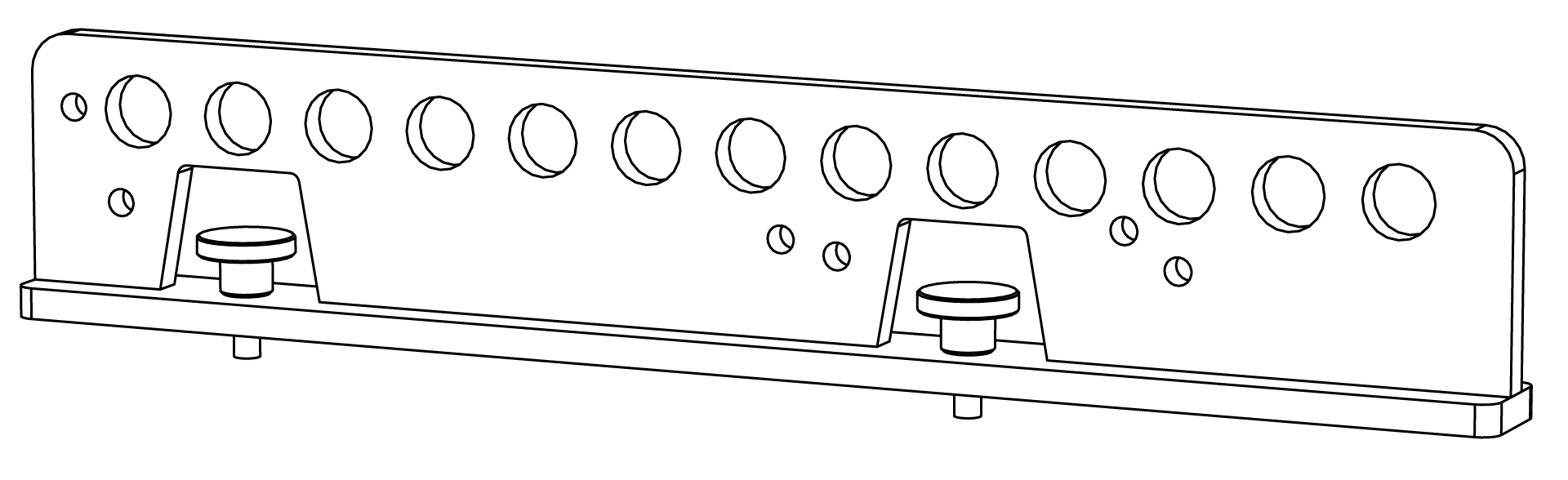 |
PRODUCT | |
Part number | 40.330.059.01 |
Function | When mounted to the top of a loudspeaker, provides attachment point(s) for 5/8-inch shackles. For vertical arrays, when mounted to the bottom of one loudspeaker and the top of another, provides attachment points for the MSK-T1 Splay Kit. |
Product compatibility | ULTRA-X80, ULTRA-X82, 1800-LFC |
MATERIALS AND FINISH | |
Primary materials | Steel |
Finish | Low gloss, weather-protected, non-textured powder-coated |
Exterior color | Black |
Custom color available | Available; mounting hardware is always black |
ENIVIRONMENTAL | |
Protection level | Ultraviolet (UV), chemical, and water-resistant |
RIGGING AND SAFETY | |
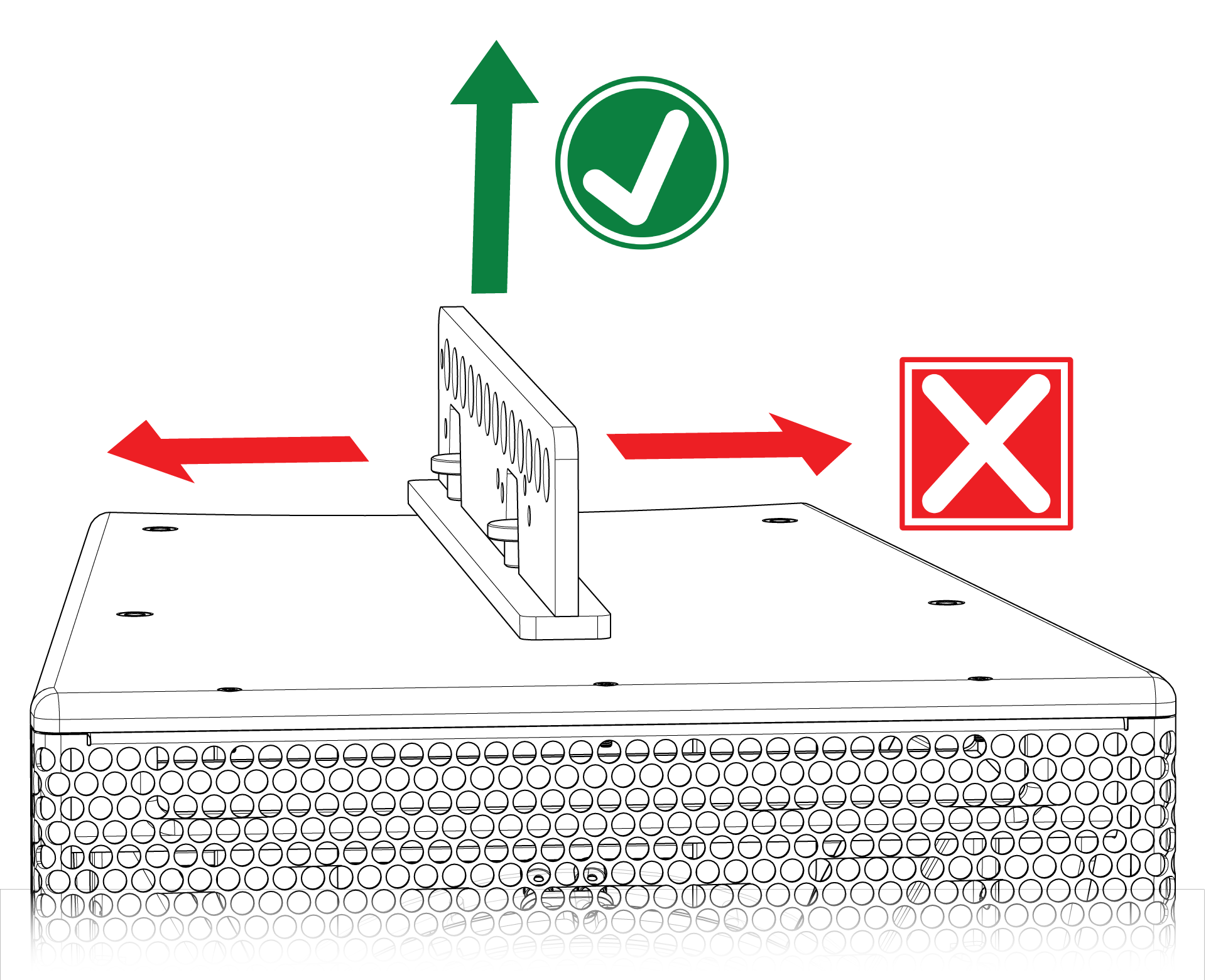
Safety restrictions | Only fasten this accessory to loudspeakers with the provided fastening hardware or replacement hardware provided by Meyer Sound Laboratories. This rigging accessory is only rated for vertical loading. Horizontal loads may damage the accessory and/or the loudspeaker mounting points. |
Rigging load capacity | Maximum three ULTRA-X80 or ULTRA-X82, two 1800-LFC, or one 1800-LFC and one ULTRA-X80 series |
Attachment Points | Thirteen suspension holes with a diameter of 0.87 in (22 mm) accept standard 5/8 in shackles. |
WEIGHTS AND MEASURES | |
Product weight | 7.8 lb (3.54 kg) |
Outer dimensions | W: 1.48 in (38 mm) x H: 3.41 in (87 mm) x D: 18.77 in (477 mm) |
CARE AND MAINTENANCE | |
Inspection | At least annually, inspect for deterioration or deformation per Safety statement for rigging. |
Cleaning | Clean with soap, water, and a sponge. |
Quantity | Part name | Meyer Sound PN |
|---|---|---|
1 | M330 Pick up bar | 45.330.061.01 |
2 | Knurled knob thumb screw, M8 x 1.25, 20mm long, black | 124.241 |
Safety statement for rigging
READ THIS STATEMENT CAREFULLY IN ITS ENTIRETY |
It contains important information regarding safety issues, including guidelines for general safe use of rigging systems as well as advisories on government regulations and liability laws.
This statement assumes that the owners and/or users of a Meyer Sound QuickFly® system are knowledgeable and experienced in the areas of rigging and flying loudspeaker systems. Many issues of crucial concern, such as the determination of appropriateness and condition of venue rigging points, cannot be addressed here. Therefore, the user must assume all responsibility for the appropriate use of QuickFly systems in any particular location or circumstance.
The suspension of large, heavy objects in public places is subject to numerous laws and regulations at the national/ federal, state/provincial, and local levels. The user must assume responsibility for making sure that use of any QuickFly system and its components in any particular circumstance or venue conforms to all applicable laws and regulations in force at the time.
Caution
This accessory is rated for vertical loading only. Do not configure the rigging bar in a manner that imposes horizontal loads on the accessory fasteners. Horizontal loading may damage the loudspeaker mounting points, the accessory, or both.
Assembly instructions
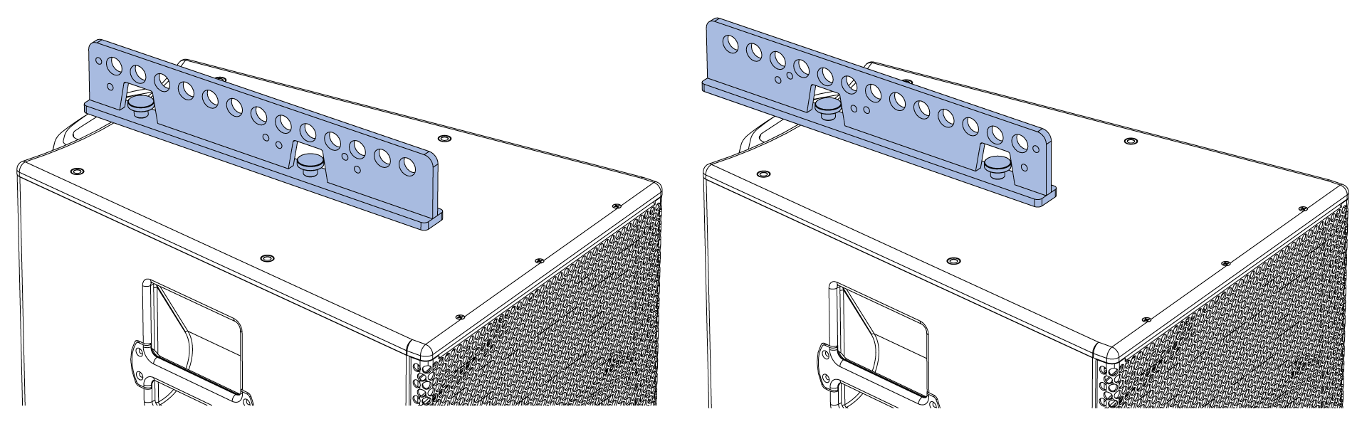
Orient the rigging bar to maximize up or down tilt.
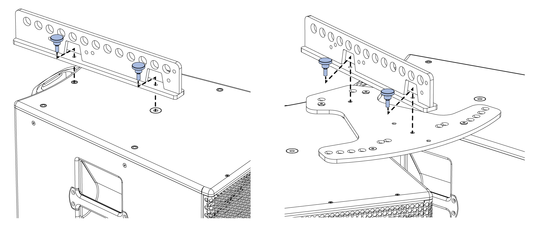
Secure each rigging bar with the provided fasteners and fully hand-tighten. For longer-term installations, apply thread locker to fastener threads before installation; thread locker not included.
Combine with the MSK-T1 Splay Kit for vertical arrays. See Accessory Datasheet — MSK-T1 Splay Kit. Combine with MCP-T1 Cluster Plate for horizontal arrays. See Accessory Datasheet — MCP-T1 Cluster Plate Kit.
For single-point suspension of ULTRA-X80 loudspeakers, the tables below list the resulting tilt angle for each of the 13 connection holes for both orientations of the rigging bar. Negative values indicate downtilt, positive values indicate uptilt.
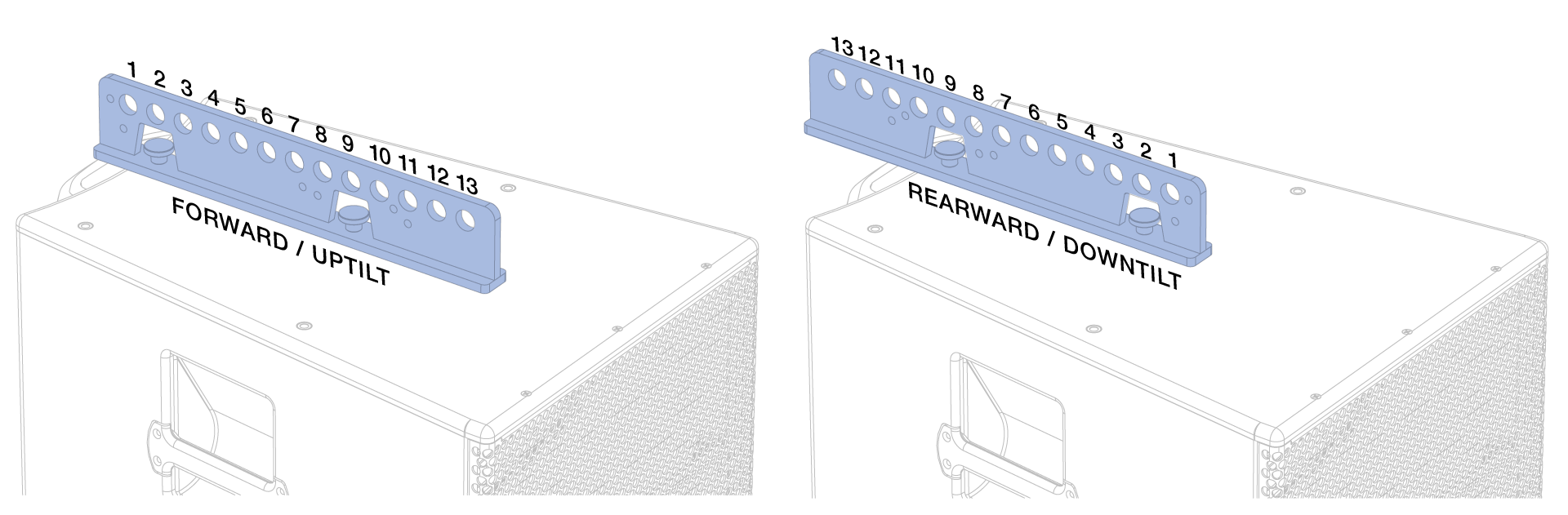
Suspension hole number | 1 | 2 | 3 | 4 | 5 | 6 | 7 | 8 | 9 | 10 | 11 | 12 | 13 |
Resulting tilt angle | -30 | -26 | -23 | -20 | -16 | -12 | -8 | -4 | 0 | +4 | +8 | +12 | +16 |
Suspension hole number | 1 | 2 | 3 | 4 | 5 | 6 | 7 | 8 | 9 | 10 | 11 | 12 | 13 |
Resulting tilt angle | +5 | +1 | -3 | -7 | -11 | -15 | -19 | -23 | -26 | -29 | -32.5 | -35 | -38 |
PN: 04.330.004.06 B 2607 |