Accessory User Guide — MSK-T1 Splay Kit
PN: 40.330.060.01 compatible with ULTRA-X80, ULTRA-X82, 1800-LFC


 |
PRODUCT | |
Part number | 40.330.060.01 |
Function | Provides splay angles of 25°, 30°, 35°, or 40° between vertically arrayed loudspeakers. |
Product compatibility | ULTRA-X80, ULTRA-X82, 1800-LFC |
MATERIALS AND FINISH | |
Primary materials | Steel |
Finish | Low gloss, weather-protected, non-textured powder coated |
Exterior color | Black |
Custom color available | Available; mounting fasteners are always black |
ENIVIRONMENTAL | |
Protection level | Ultraviolet (UV), chemical, and water-resistant |
RIGGING AND SAFETY | |
Safety restrictions | Only fasten to MRB-T1 Rigging Bars with the provided fastening hardware or replacement hardware provided by Meyer Sound Laboratories. This rigging accessory is only rated for vertical loading. Horizontal loads may damage the accessory and/or the loudspeaker mounting points. |
Rigging load capacity | Supports up to three ULTRA-X80 series loudspeakers, or one 1800-LFC and one ULTRA-X80 series loudspeaker |
WEIGHTS AND MEASURES | |
Product weight | 3.2 lb (1.2 kg) |
Outer dimensions | W: 2.23 in (57 mm) x H: 18.08 in (459 mm) x D: 21.82 in (554 mm) with front link in 40-degree position |
CARE AND MAINTENANCE | |
Inspection | At least annually, inspect for deterioration or deformation per Safety statement for rigging. |
Cleaning | Clean with soap, water, and a sponge. |
Quantity | Part name | Meyer Sound PN |
|---|---|---|
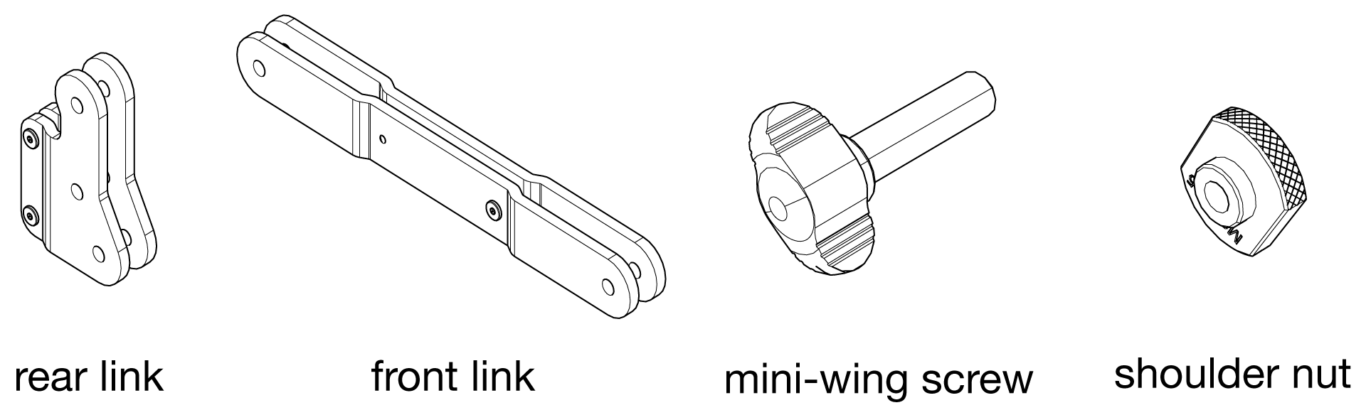
1 | Rear link assembly | 45.330.068.01 |
2 | Front link assembly | 45.330.063.01 |
5 | Screw, mini-wing, M8 x 1.25, 30 mm, stainless, black | 124.242 |
5 | Shoulder nut, knurled, M8 x 1.25, stainless, black oxide | 61.010.455.01 |
When installing Meyer Sound loudspeakers, always observe the following precautions:
Use all Meyer Sound products in accordance with local, state, federal, and industry regulations. Owners and users must evaluate the reliability of any rigging or mounting method for their application. Rigging loudspeakers requires trained and experienced professionals.
Use mounting and rigging hardware rated to meet or exceed the suspended weight.
Make sure to attach mounting hardware to the building's structural components (studs or joists), and not just to the wall surface. Verify that the building's structure and the anchors used for the installation will safely support the total weight of the mounted loudspeakers.
Use mounting hardware appropriate for the installation surface.
Tighten bolts securely. Meyer Sound recommends using Loctite® on bolt threads and safety cables.
Inspect mounting and rigging hardware regularly. Immediately replace any worn or damaged components.
Caution
This accessory is rated for vertical loading only. Do not configure the rigging bar/splay kit assembly in a manner that imposes horizontal loads on the accessory fasteners. Horizontal loading may damage the loudspeaker mounting points, the accessory, or both.
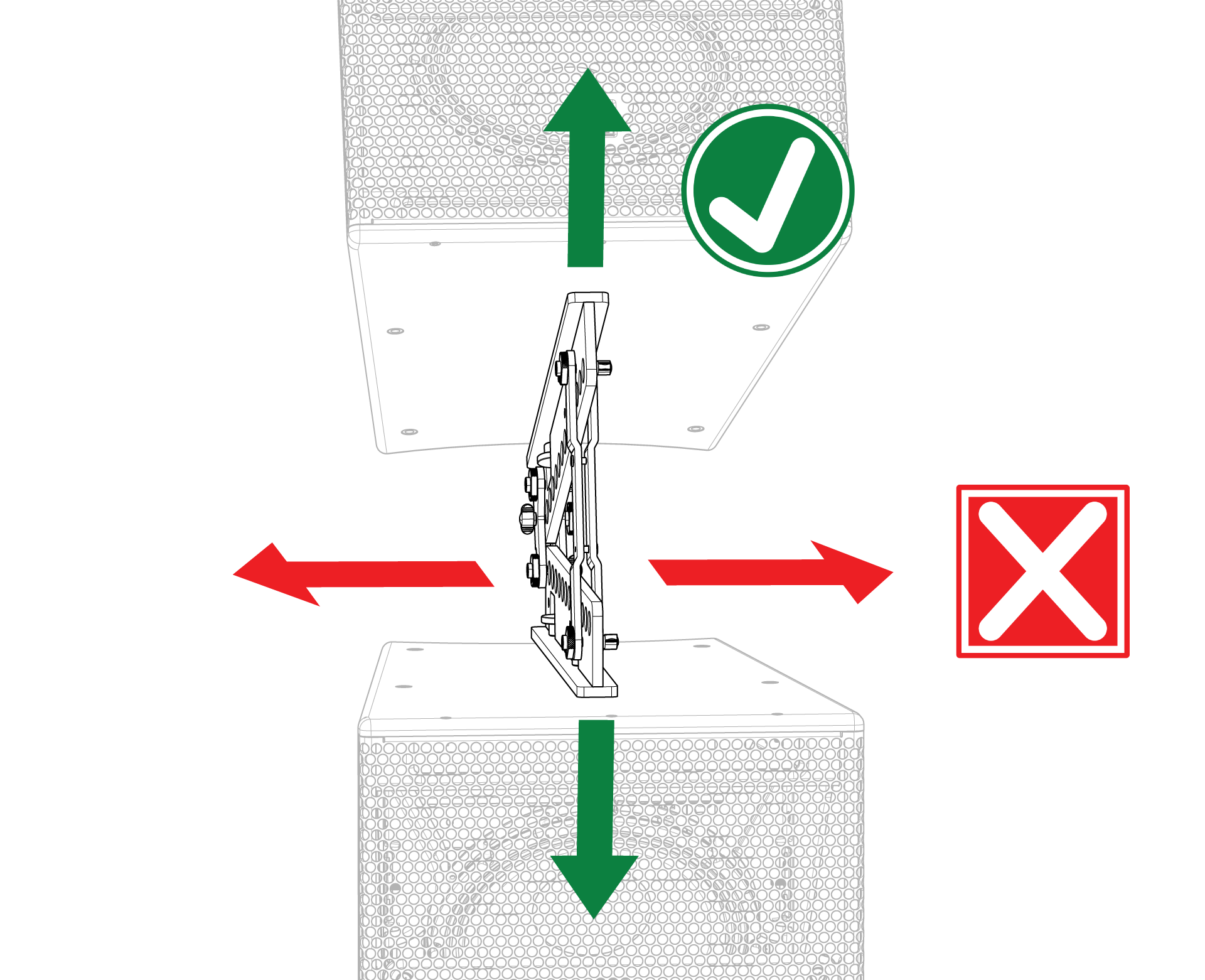
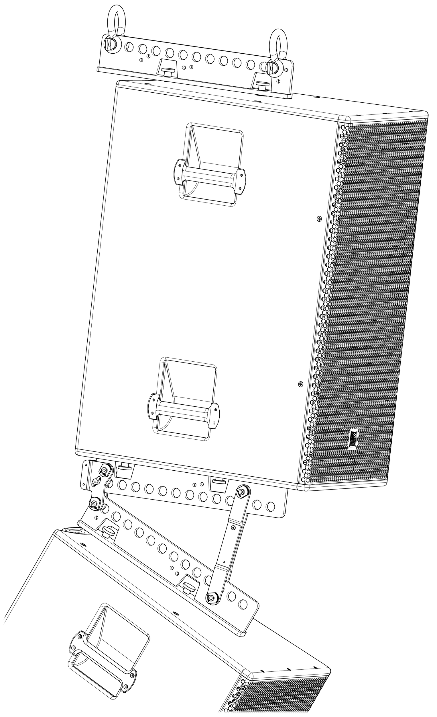
The MSK-T1 Splay Kit provides splay between two MRB-T1 Rigging Bars. The rear link is the rotation point.
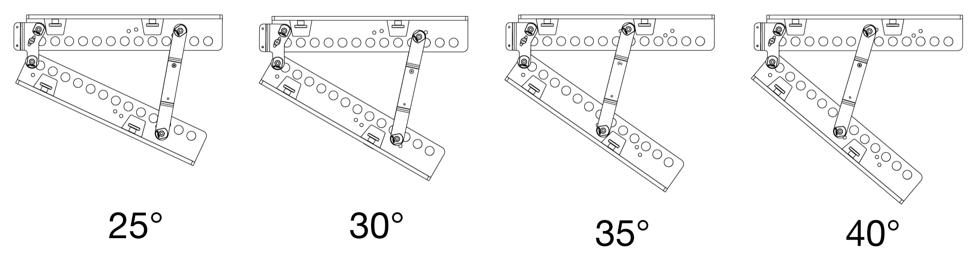
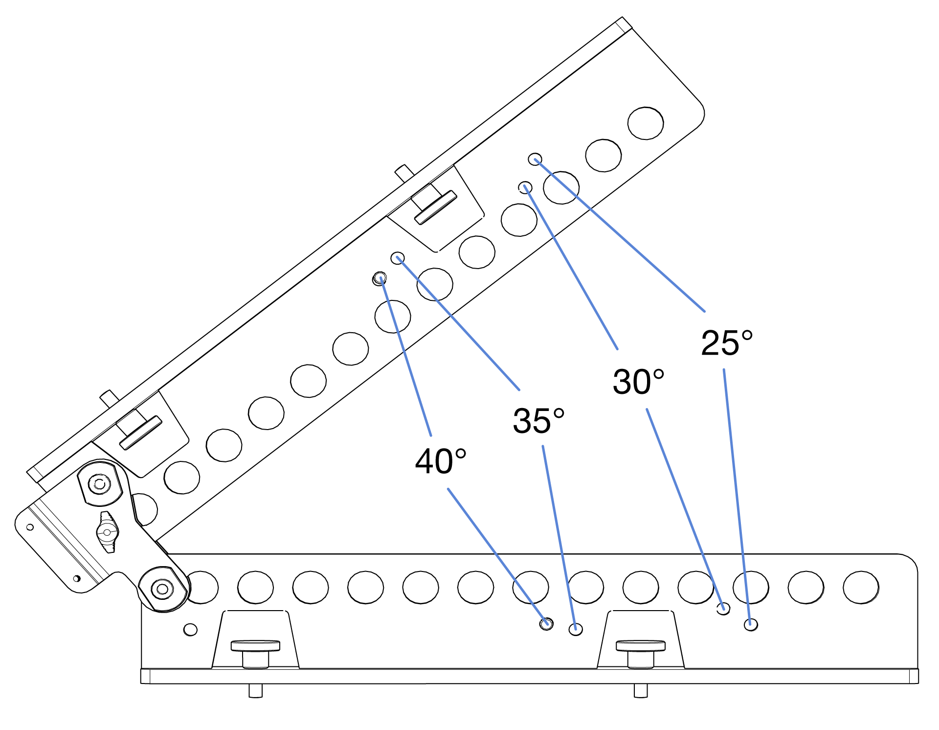
The front link mounting location determines the splay angle between the rigging bars.
Assembly instructions
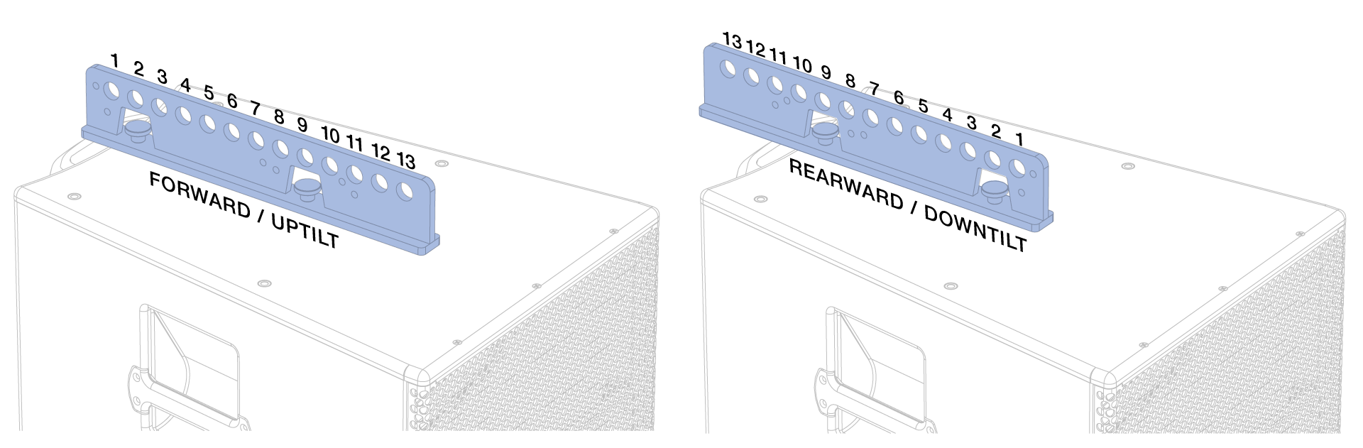
Fasten the MRB-T1 Rigging Bars to loudspeakers per their assembly instructions. For all link kit configurations, secure the rigging bars to the loudspeakers in the forward position to align the front and rear splay link mounting points correctly.
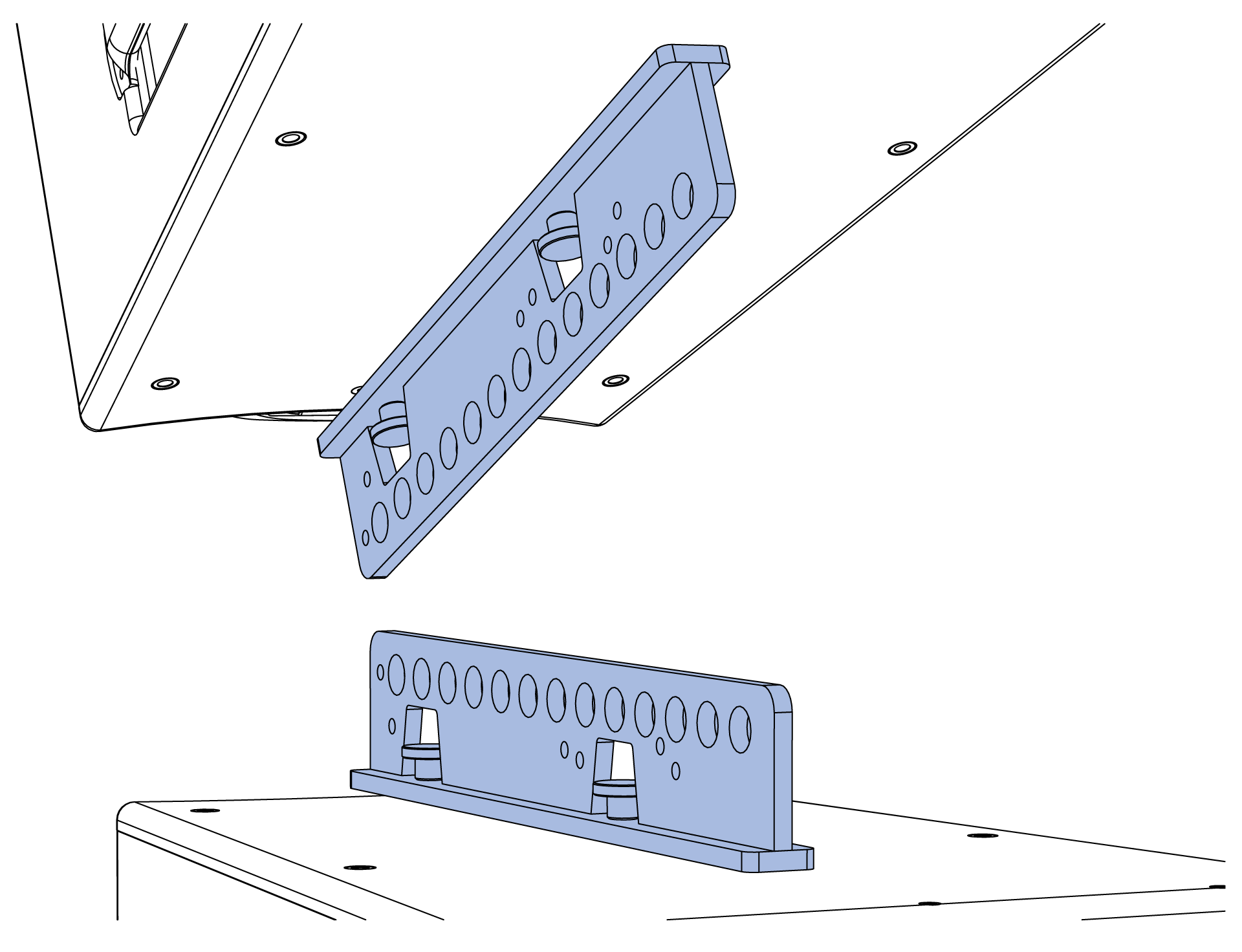
Align the upper two mounting holes of the rear link with the two holes at the end of the upper rigging bar. Secure the rear link to the rigging bar with two mini-wing screws and shoulder nuts. Orient the screws opposite each other to provide more hand space to tighten them.
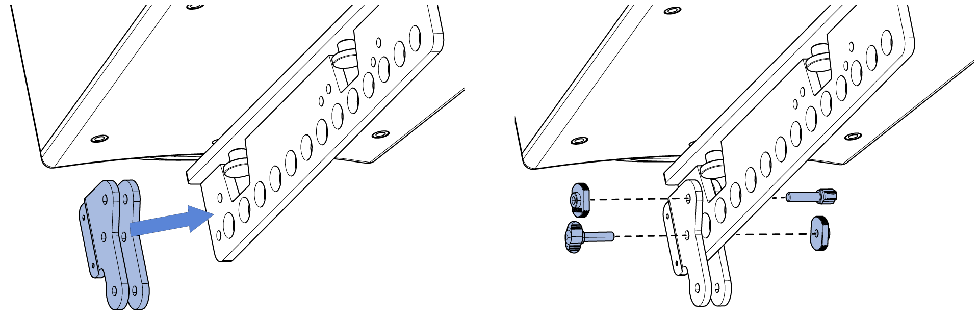
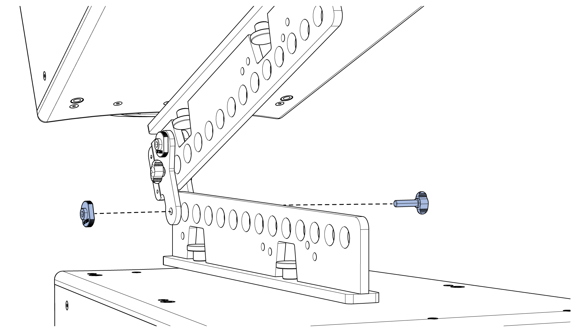
Secure the rear link to the lower rigging bar with a mini-wing screw and a shoulder nut.
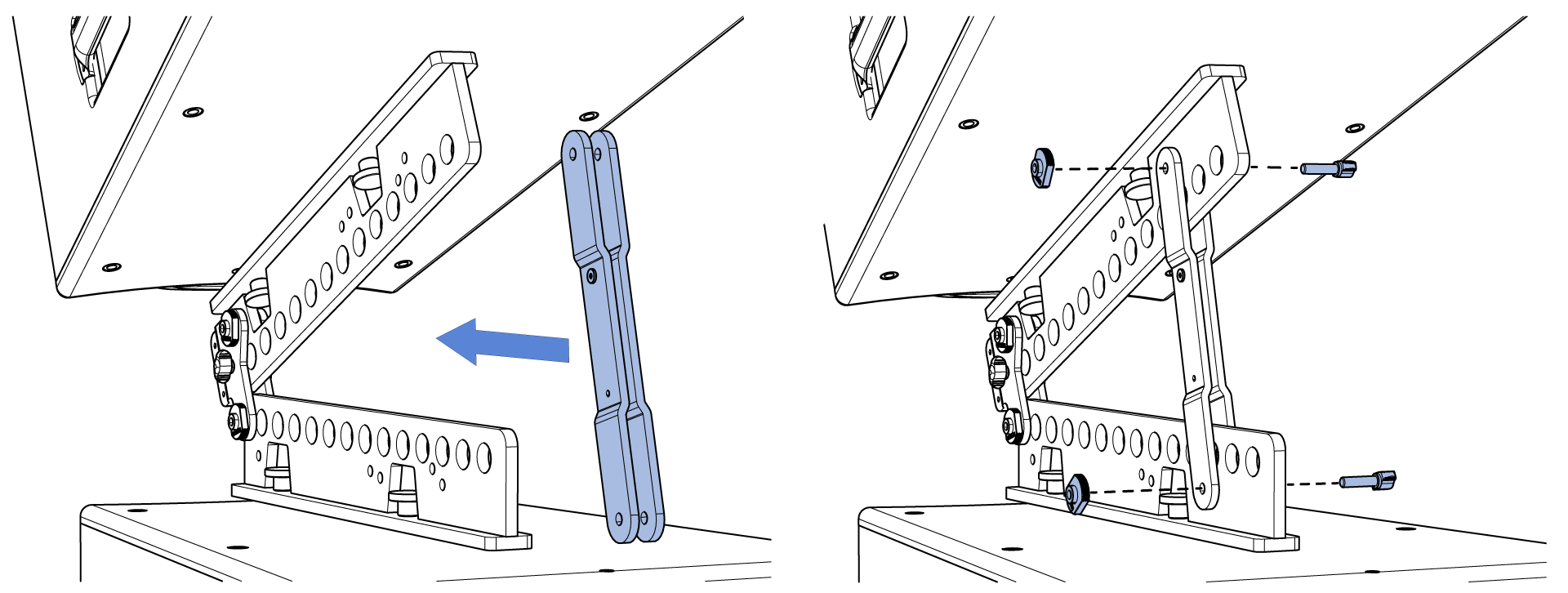
Align the mounting holes of the front link with the holes on the rigging bar for the desired splay angle and attach with two mini-wing screws and shoulder nuts, 25° splay position illustrated below.
Configurations
Deploy the splay kit between two or three ULTRA-X80 series loudspeakers. The two-loudspeaker configurations below exceed 5:1 safety limits when suspended from the MRB-T1. For three-loudspeaker configurations, contact Technical Support to verify safety limits and component capacities: meyersound.com/contact.
Suspend the rigging bar from two locations to facilitate horizontal array aiming. Always suspend the array with the MRB-T1 Rigging Bar. Meyer Sound has not evaluated or qualified any other method or hardware.
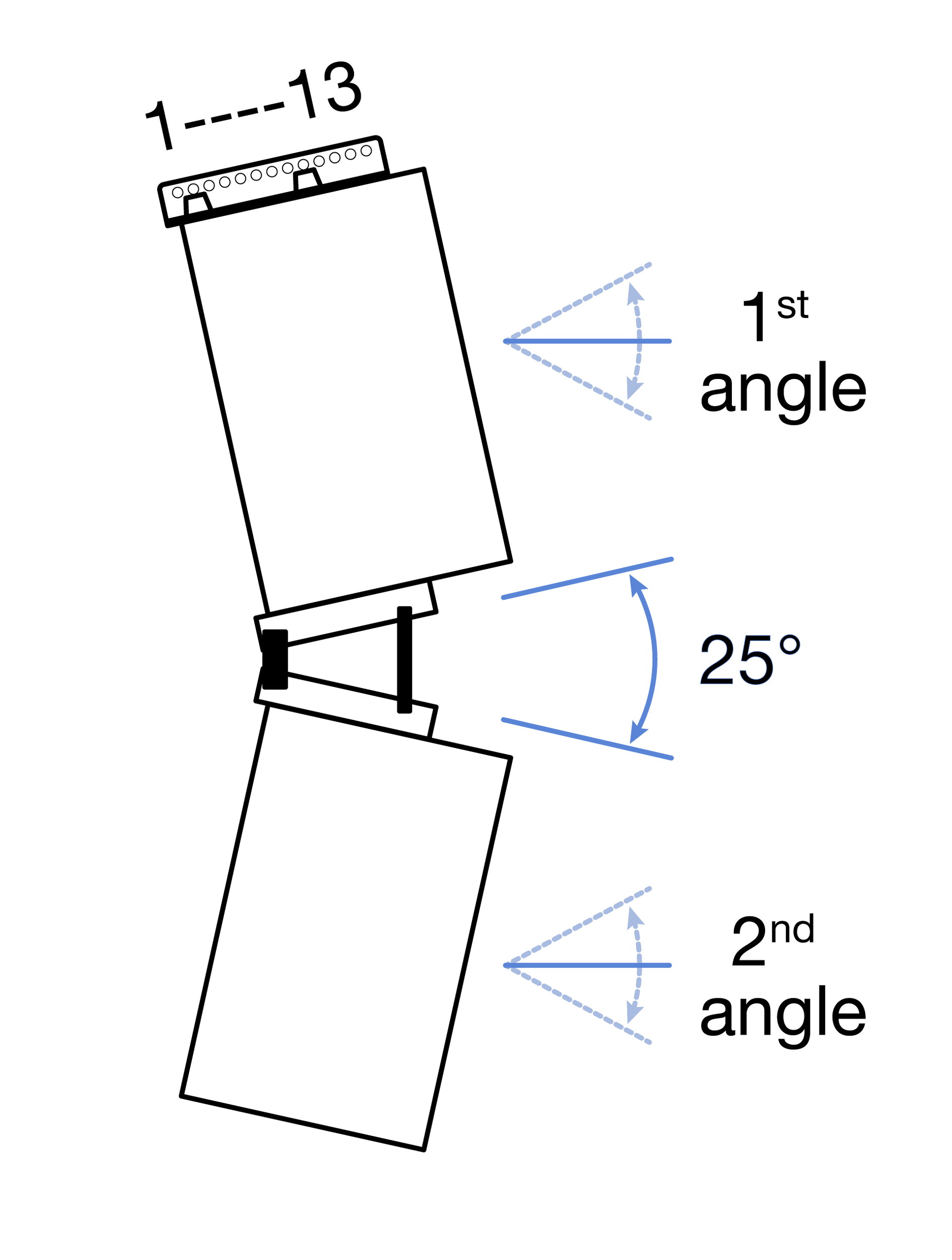
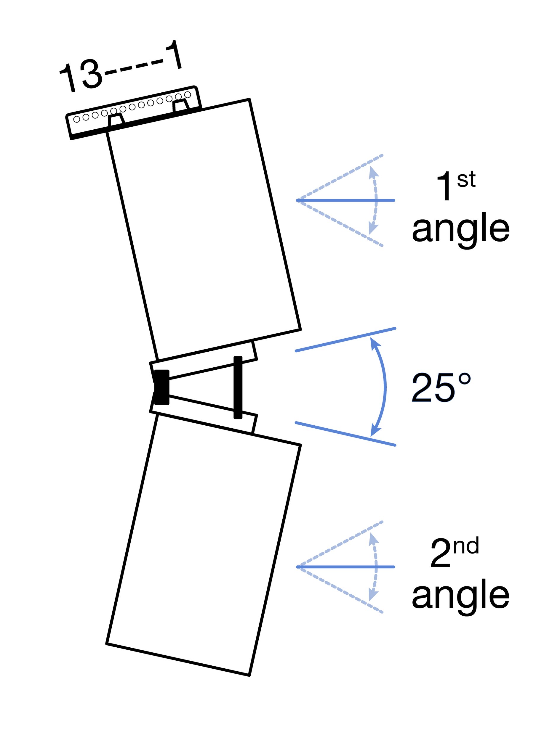
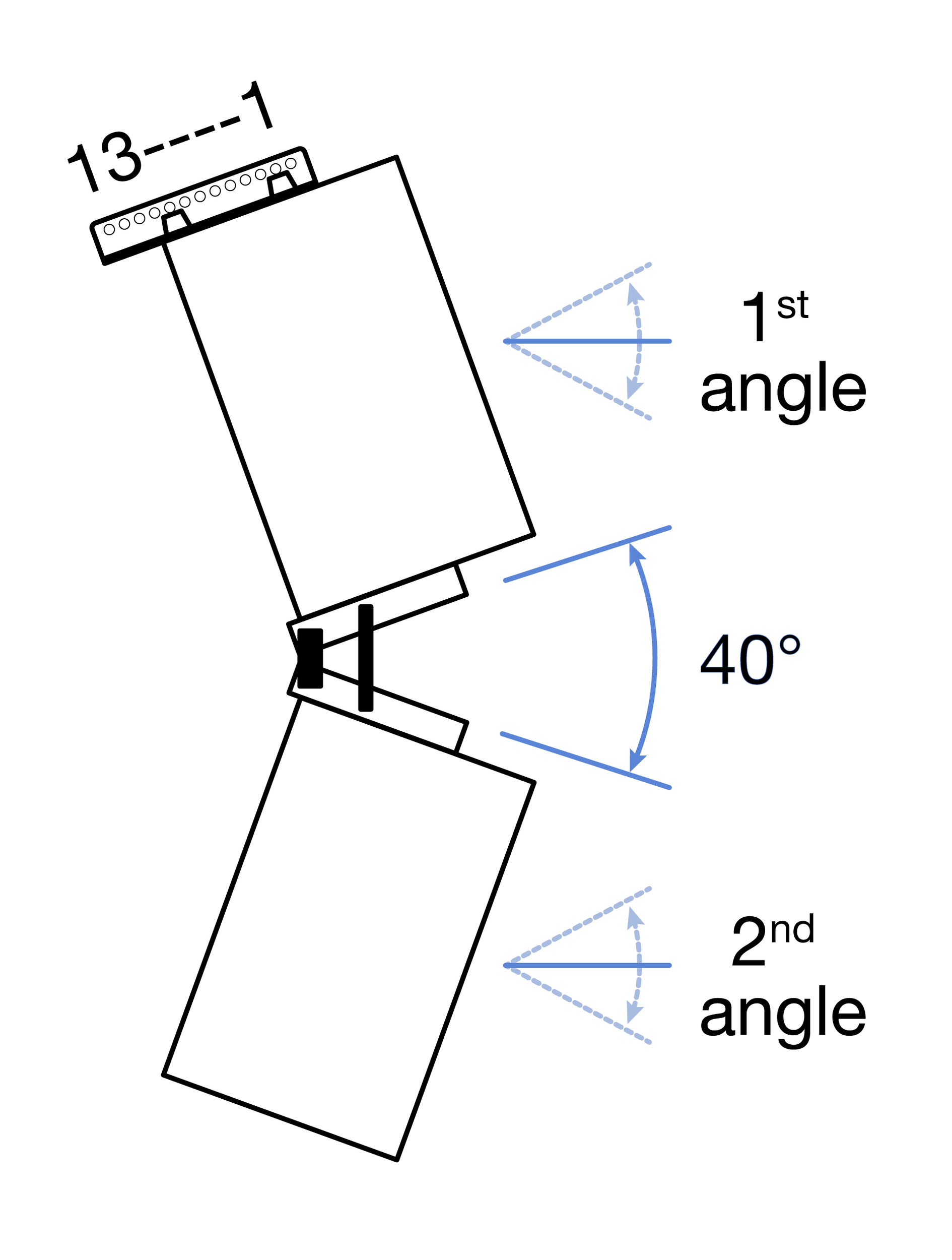
For arrays of two ULTRA-X80 loudspeakers, the tables below list the result tilt of the top and bottom loudspeakers when the rigging bar is suspended from a single point. The MRB-T1 row lists the suspension positions (1-13). The 1st and 2nd angle rows list the result up (+) or down (-) tilt of the loudspeakers.
| MRB-T1 | 1 | 2 | 3 | 4 | 5 | 6 | 7 | 8 | 9 | 10 | 11 | 12 | 13 | |
1st angle | -9 | -7 | -5 | -3 | -1 | +1 | +3 | +5 | +6 | +8 | +10 | +12 | +14 | ||
2nd angle | -34 | -32 | -30 | -28 | -27 | -25 | -23 | -21 | -19 | -17 | -15 | -14 | -12 |
| MRB-T1 | 1 | 2 | 3 | 4 | 5 | 6 | 7 | 8 | 9 | 10 | 11 | 12 | 13 | |
1st angle | +8 | +7 | +5 | +3 | +1 | -1 | -3 | -5 | -7 | -9 | -11 | -12 | -14 | ||
2nd angle | -17 | -19 | -21 | -22 | -24 | -26 | -28 | -30 | -32 | -34 | -36 | -37 | -39 |
| MRB-T1 | 1 | 2 | 3 | 4 | 5 | 6 | 7 | 8 | 9 | 10 | 11 | 12 | 13 | |
1st angle | -8 | -6 | -4 | -2 | 0 | +2 | +4 | +6 | +8 | +10 | +11 | +13 | +15 | ||
2nd angle | -38 | -36 | -34 | -32 | -30 | -28 | -26 | -24 | -23 | -21 | -19 | -17 | -16 |
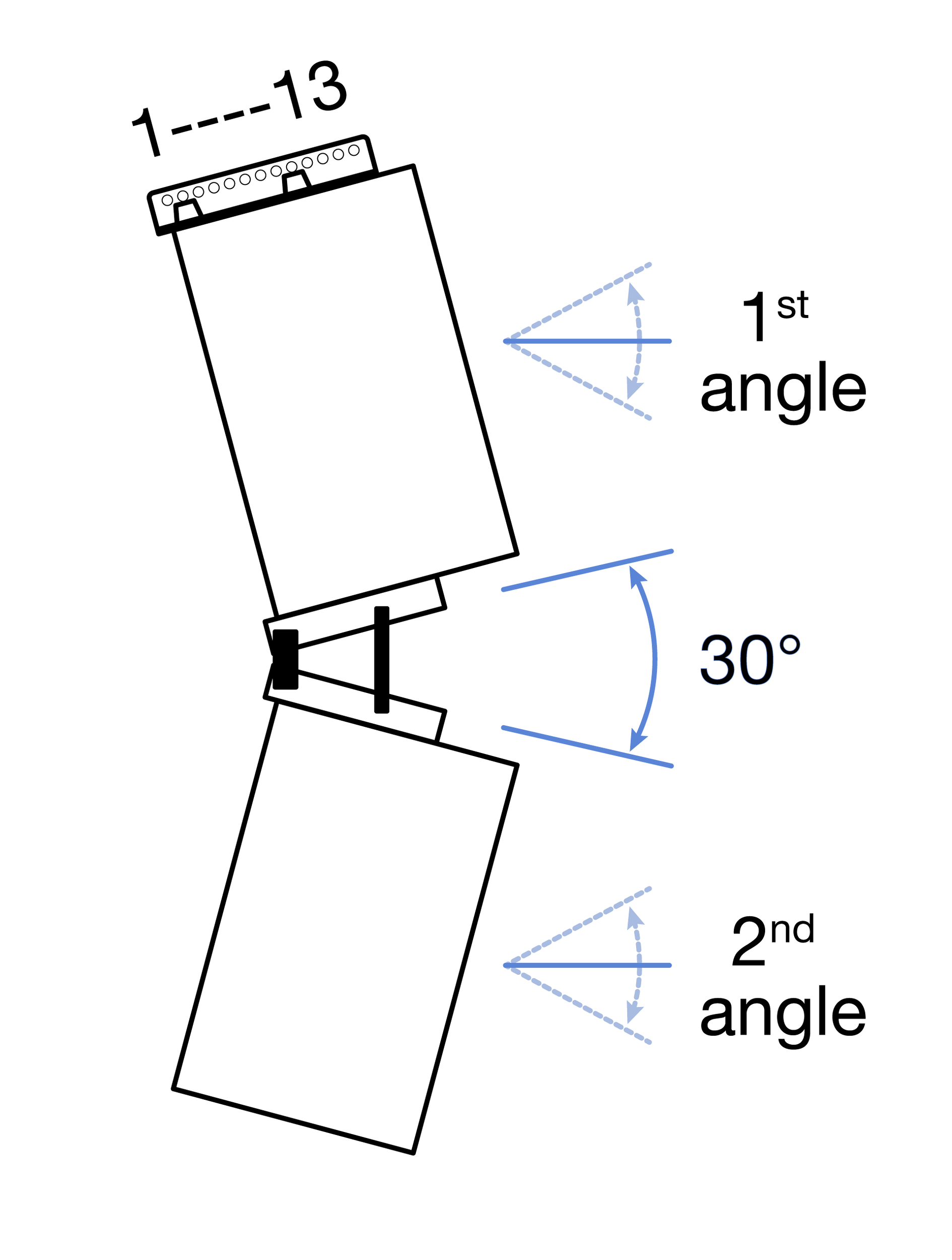
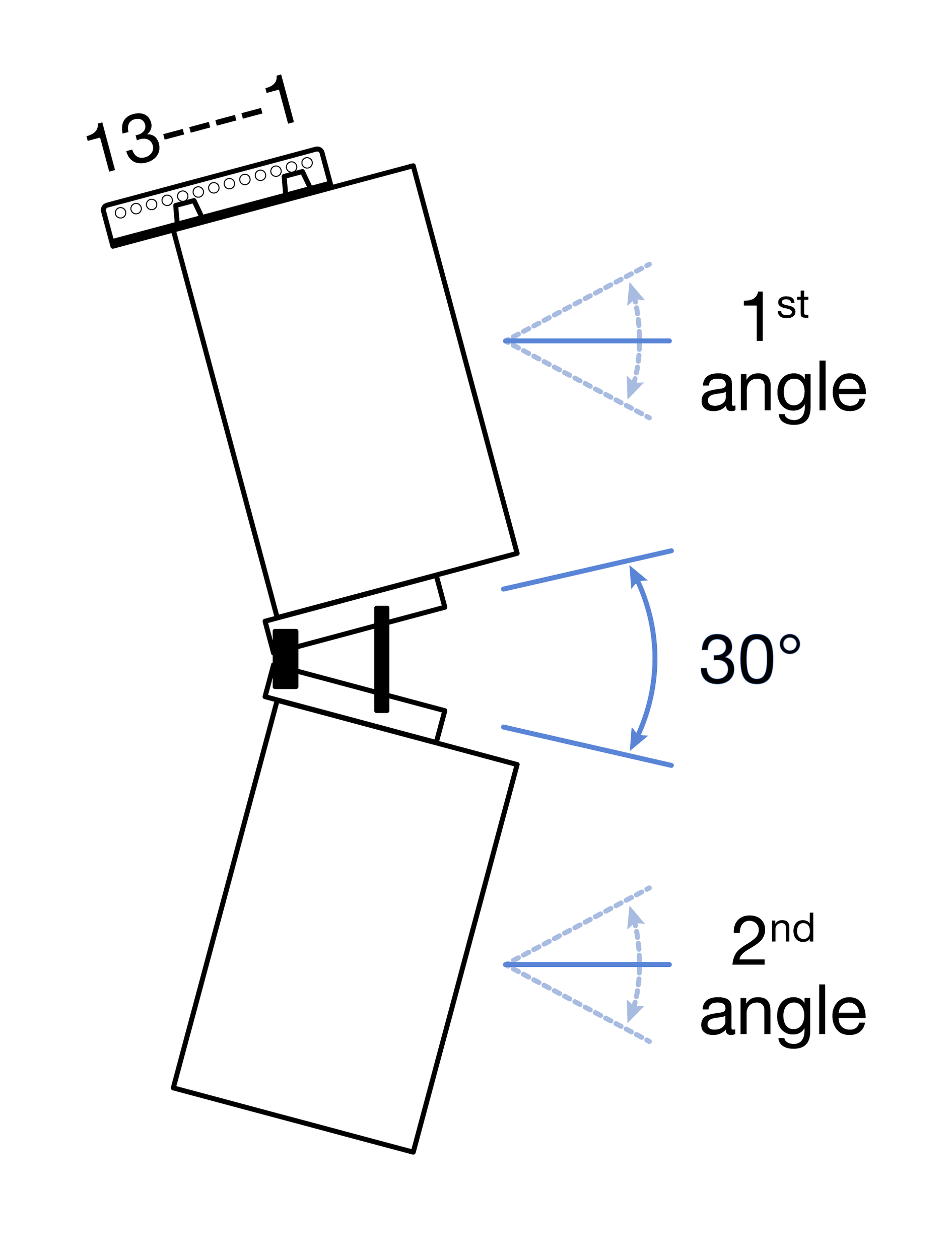 | MRB-T | 1 | 2 | 3 | 4 | 5 | 6 | 7 | 8 | 9 | 10 | 11 | 12 | 13 |
1st angle | +10 | +8 | +6 | +4 | +2 | 0 | -2 | -4 | -6 | -8 | -9 | -11 | -13 | |
2nd angle | -21 | -22 | -24 | -26 | -28 | -30 | -32 | -34 | -36 | -37 | -39 | -41 |
| MRB-T1 | 1 | 2 | 3 | 4 | 5 | 6 | 7 | 8 | 9 | 10 | 11 | 12 | 13 | |
1st angle | -6 | -5 | -3 | 0 | +1 | +3 | +5 | +7 | +9 | +11 | +13 | +14 | +16 | ||
2nd angle | -41 | -39 | -37 | -36 | -34 | -32 | -30 | -28 | -26 | -25 | -23 | -21 | -19 |
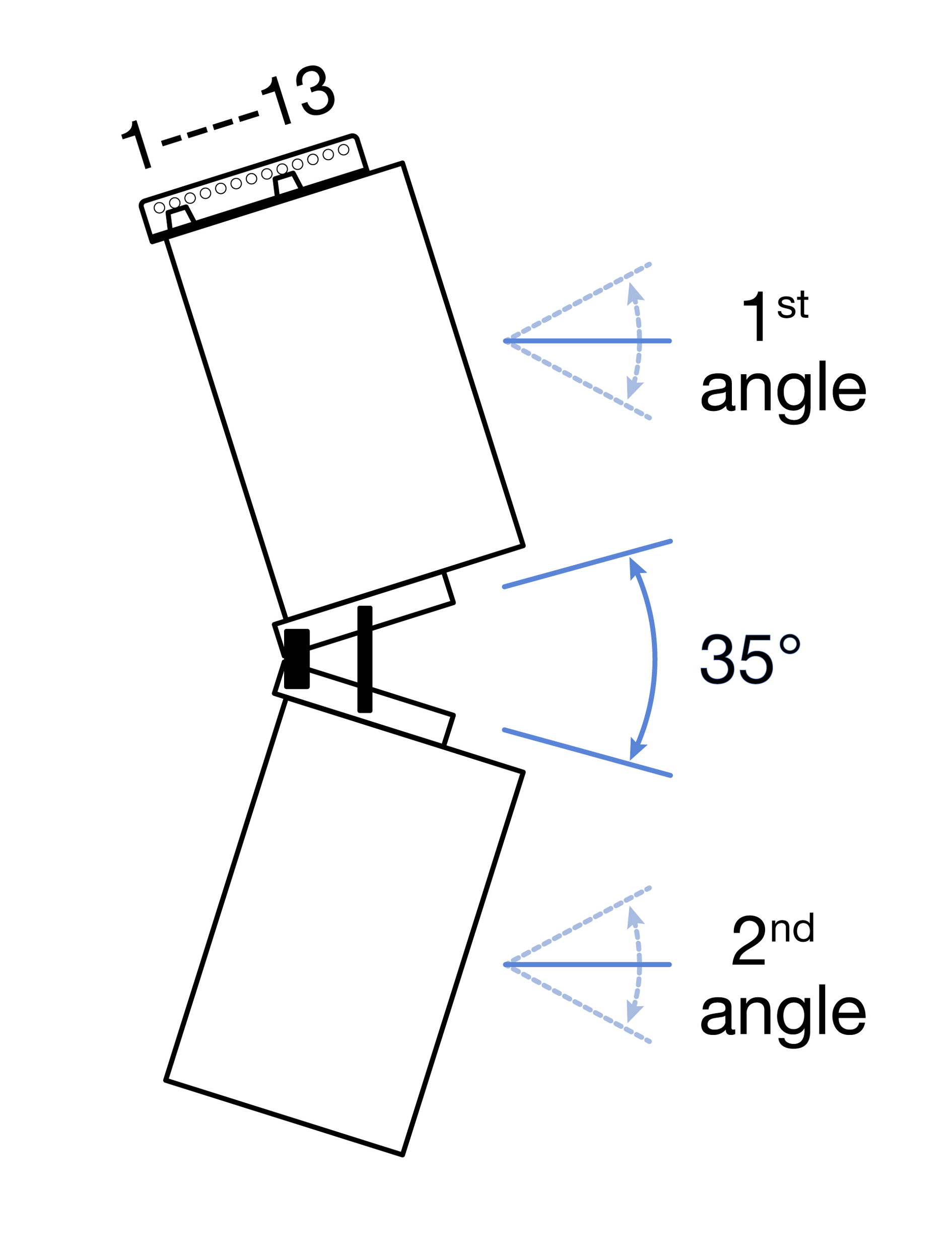
| MRB-T1 | 1 | 2 | 3 | 4 | 5 | 6 | 7 | 8 | 9 | 10 | 11 | 12 | 13 | |
1st angle | +11 | +9 | +7 | +5 | +3 | +1 | 0 | -3 | -5 | -6 | -8 | -10 | -12 | ||
2nd angle | -24 | -26 | -28 | -30 | -31 | -33 | -35 | -37 | -39 | -41 | -43 | -45 | -47 |
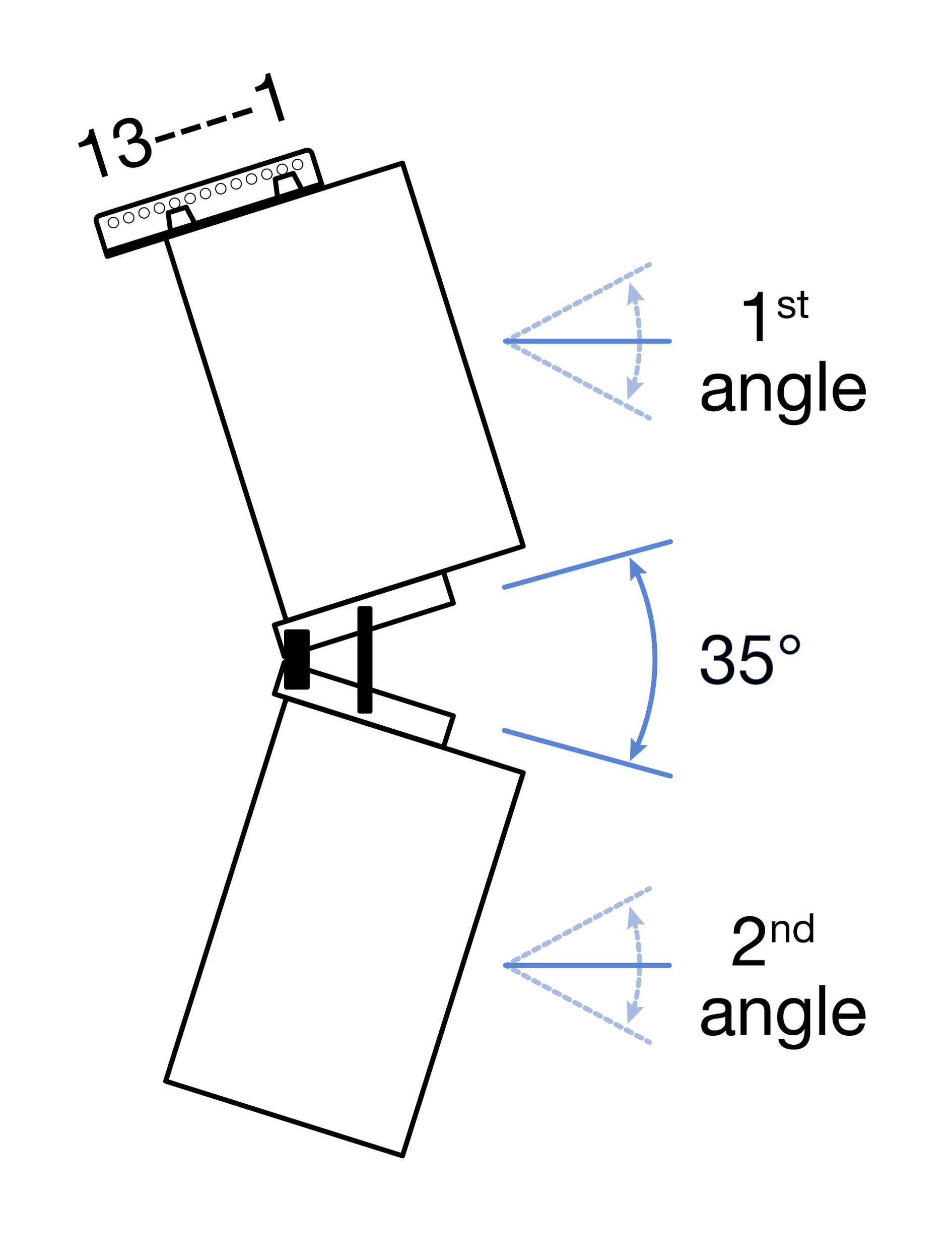
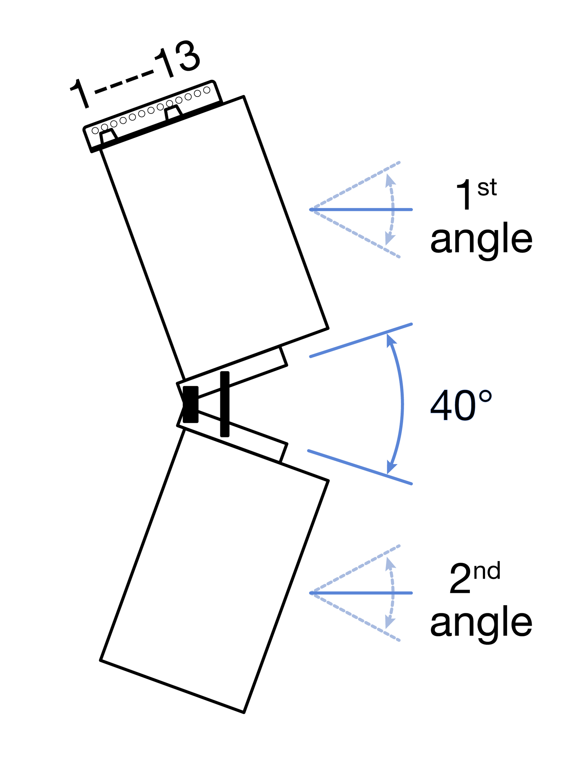 | MRB-T1 | 1 | 2 | 3 | 4 | 5 | 6 | 7 | 8 | 9 | 10 | 11 | 12 | 13 |
1st Angle | +17.4 | +15.6 | +13.8 | +11.8 | +10.1 | +8.2 | +6.4 | +4.4 | +2.4 | +0.4 | -1.4 | -3.3 | -5.2 | |
2nd angle | -23.3 | -24.7 | -26.3 | -28.1 | -29.9 | -31.7 | -33.4 | -35.4 | -37.2 | -39.2 | -41.0 | -42.9 | -44.8 |
| MRB-T1 | 1 | 2 | 3 | 4 | 5 | 6 | 7 | 8 | 9 | 10 | 11 | 12 | 13 | |
1st Angle | -5 | -3 | -1 | 0 | +2 | +4 | +6 | +8 | +10 | +12 | +14 | +16 | +17 | ||
2nd angle | -45 | -43 | -41 | -39 | -37 | -35 | -33 | -32 | -30 | -28 | -26 | -25 | -23 |
PN: 04.330.004.07 B 2608 |
PN: 05.330.060.01 A 2608 |